125
DVP-CX777ES
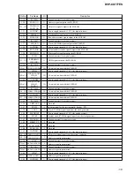
Pin No.
Pin Name
I/O
Description
123
WCK
I
Operation clock signal input for PSP physical disc mark detection from the DSP
124, 125
WAVDD0,
WAVDD1
—
A/D power supply terminal (+2.5V) (for PSP physical disc mark detection)
126
WARFI
I
Analog RF signal input for PSP physical disc mark detection from the RF amplifier
127
WAVRB
I
A/D bottom reference terminal for PSP physical disc mark detection
128, 129
WAVSS0, WAVSS1
—
A/D ground terminal (for PSP physical disc mark detection)
130
VSIO
—
Ground terminal (for I/O)
131 to 134
DQ7 to DQ4
I/O
Two-way data bus with the SD-RAM
135
VDIO
—
Power supply terminal (+3.3V) (for I/O)
136 to 139
DQ3 to DQ0
I/O
Two-way data bus with the SD-RAM
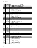
140
VSIOA3
—
Ground terminal (for I/O)
141
DCLK
O
Clock signal output to the SD-RAM
142
DCKE
O
Clock enable signal output to the SD-RAM
143
XWE
O
Write enable signal output to the SD-RAM
144
XCAS
O
Column address strobe signal output to the SD-RAM
145
XRAS
O
Row address strobe signal output to the SD-RAM
146
VDIO
—
Power supply terminal (+3.3V) (for I/O)
147
TESTO
O
Output terminal for the test
148, 149
A11, A10
O
Address signal output to the SD-RAM
150
VSC
—
Ground terminal (for core)
151, 152
A9, A8
O
Address signal output to the SD-RAM
153
VDC
—
Power supply terminal (+2.5V) (for core)
154 to 157
A7 to A4
O
Address signal output to the SD-RAM
158
VSIO
—
Ground terminal (for I/O)
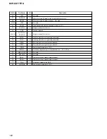
159 to 162
A3 to A0
O
Address signal output to the SD-RAM
163
VDIO
—
Power supply terminal (+3.3V) (for I/O)
164
XSRQ
O
Stream data bus request signal output to the DSP
165
XSHD
I
Stream data bus header flag signal input from the DSP
166
SDCK
I
Stream data bus clock signal input from the DSP
167
XSAK
I
Stream data bus acknowledge signal input from the DSP
168
SDEF
I
Stream data bus error flag signal input from the DSP
169 to 176
SD0 to SD7
I
Stream data signal input from the DSP

