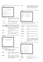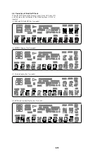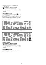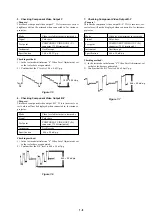
6-24
1-3-2.
When the 33 MHz signal appears at CPUCK
• WAIT signal check
Observe XWAIT (pin-
yj
) of SYSCON (IC104) with an os-
cilloscope.
If it is fixed to “L” (0V).
t
Observe CS2X to CS5X (pins-
y;
to
yd
).
If CS2X or CS3X is “L”.
t
AVD (IC403) has defective sol-
dering or AVD is defective.
If CS4x or CS5X is “L”.
t
ARP & SERVO (IC301) has
defective soldering or ARP & SERVO is defective.
If any one of the above is not “L”.
t
XWAIT or CSnX is
short-circuited or has the defective soldering or AVD (IC403)
is defective or ARP & SERVO (IC301) is defective.
Center voltage
t
The XWAIT line has defective soldering
or is short-circuited or AVD (IC403) is defective or ARP &
SERVO (IC301) is defective or SYSCON (IC104) is defec-
tive.
• CSnX signal check
Observe CS0X to CS5X (pins-
tk
to
yd
) of SYSCON (IC104)
with an oscilloscope.
If they are fixed to “L” (0V) or if to center voltage
t
Check
that the ICs do not have the defective soldering or is short-
circuited with the other signal lines or SYSCON (IC104) is
defective.
CS0X: ROM (IC106 or IC107)
CS2X, CS3X: AVD (IC403)
CS4X, CS5X: ARP & SERVO (IC301)
If the trouble symptom does not apply to any of the above phe-
nomenon, SYSCON (IC104) or ROM (IC106 or IC107) is defec-
tive.
2. Test mode menu is displayed but the machine stops
when menu is selected
2-1. AVD (IC403) check
Observe SDCLKO (pin-
<zxm
) of AVD (IC403) with an oscillo-
scope.
95 MHz
t
No problem
27 MHz
t
Observe the XRST, HA, HD, XRD, XWRH INT
and CS signal waveform at the respective pins of AVDEC,
AVD (IC403) is defective.
If the signal is other than the above frequencies
t
AVD
(IC403) 27MHz signal line (CLKI (pin-
<zb,
), SCLKIN (pin-
<zn/
)) is short-circuited, IC mount is defective, AVD (IC403) is
defective, PLL (IC103) is defective.
2-2. INT signal check
Observe INT0 to 2 (pins-
qh
to
qk
) of SYSCON (IC104) with
an oscilloscope.
If they are fixed to “L” (0V) or fixed to the center voltage
t
Check that the ICs do not have the defective soldering, or are
short-circuited, SYSCON (IC104) is defective, or the follow-
ing ICs are not defective.
INT0: AVD (IC403)
INT1, INT2: ARP & SERVO (IC301)
2-3. If any abnormality cannot be confirmed by the
above-described checks, check the CS signal that
is currently output.
The CS signal other than CS0X is being output.
t
IC mount
is defective or the IC is defective depending on the moving
CS signal.
CS2X, CS3X: AVD (IC403)
CS4X, CS5X: ARP & SERVO (IC301)
If the trouble is not applicable to any of the above phenomenon,
SYSCON (IC104) or ROM (IC106 or IC107) is defective.
3. If the message “SDSP No Ack” appears after the menu
is displayed.
3-1. ARP & SERVO clock signal check
Check frequency of CLKIN (pin-
<zb/
)
33 MHz
t
Normal
Frequency other than 33 MHz
t
CLKIN is short-circuited
or defective soldering or PLL (IC103) is defective or ARP &
SERVO (IC301) is defective
3-2. ARP & SERVO (IC301) PLL oscillation check
Observe PLCKO (pin-
ij
) of ARP & SERVO (IC301) with an
oscilloscope.
If the pin is fixed to either “L” (0V) or “H” (3.3V).
If XRST if fixed to “L”. XRST has the defective solder-
ing, In all other cases. ARP & SERVO (IC301) is defec-
tive
If it is oscillating.
HA [0 to 7] are HD [8 to 15] are short-circuited, check
XSDSPIT and XSDSPCS or ARP & SERVO (IC301) is
defective.
4. If trouble occurs at the specific item of the “Diag All
Check”.
IC mount of the NG item is defective or IC is defective.
5. Picture and audio are not output.
Check connection of CN601, CN501
Check for the defective connection of flat cable and check of
damage of the flat cable.
6. Picture is output but audio is not output.
Check the audio data output (at pins-
wf
,
wk
, and
wl
) of AVD
(IC403)
The audio data is not output.
t
AVD (IC403) or audio
DAC (IC503) mount is defective or power supply is defec-
tive or AVD (IC403) or audio DAC (IC503) is defective.
PLL (IC103) 512fs output check
If the frequency or waveform has abnormality.
t
The sig-
nal line has defective soldering or the signal line is short-
circuited with other signal lines or PLL (IC103) is defec-
tive.
7. Audio is output but picture is not output.
Observe pins-
ej
,
ek
,
el
,
rs
,
rd
and
rf
of VDAC (IC604)
with an oscilloscope.
If the analog signal is not output.
t
The signal line has the
defective soldering or is short-circuited or parts are defective
or VDAC (IC604) is defective.
6-11-3. Drive Auto Adjustment stops due to error.
The ARP & SERVO (IC301) analog circuit of MB-107 board is
defective or RF-Amp (IC201) or M-Driver (IC202) peripheral cir-
cuit is defective or optical pickup block is defective or flat cable
connection is defective
6-11-4. The product itself is defective.
• If MB-107 does not have any problem,
The board other than MB-107 board is defective or connec-
tion is defective or optical pickup block is defective or mecha-
nism deck is defective
1. Power LED does not light in Red when the AC power
is turned on.
Check the EVER –11V (pin-
1
), EVER+5V (pin-
5
), EVER
+11V (pin-
4
) voltage of the power supply block CN201.
If voltage is abnormal.
t
The power supply block is defec-
tive.


