7-7
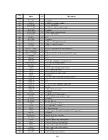
7-2. FRONT MICOM PIN FUNCTION (MAIN BOARD IC701: HMS81C1816B)
Pin
Name
I/O
Description
number
1
BUZ/RB1
(-)
N.C.
2
INT0/RB2
I
M_REQ (Main maicon/IC501 chip select)
3
INT1/RB3
I
POWER switch ON/OFF detection input
4
PWM0/COMP0/RB4
I
M_REQ (Main maicon/IC501 chip select)
5
PWM1/COMP1/RB5
(-)
N.C.
6
EC1/RB6
I
Remocon Select (Fixed at “L”)
7
TMR20V/RB7
O
Remocon Select (Fixed at “L”)
8
RE6
O
PWRCTL_3.3V (+3.3V power supply control)
9
RE5
O
/M_RESET (Master reset)
10
RE4
(-)
N.C.
11
RE3
I
I_FAST (Reference voltage of IC601 detection)
12
RE2
O
CH_EN (The change-control of DC-input or Battery-DC.)
13
RE1
I
HOLD switch detection.
14
RE0
I/O
Select2 (Fixed at “Open”)
15
RC0
O
CHARGE LED, light control.
16
RC1
O
POWER LED, light control.
17
RC2
(-)
N.C.
18
SRDYIN/SRDYOUT/RC3
(-)
N.C.
19
RC4/SCK
I
VFD_SCK (Main maicon/IC501 communication clock signal)
20
RC5/SIN
I
VFD_TXD (Main maicon/IC501 communication signal)
21
RC6/SOUT
O
VFD_RXD (Main maicon/IC501 communication signal)
22
RC7
(-)
N.C.
23
RD0/INT2
I
The wakeup signal input by DC and Battery voltage.
24
RD1/INT3
I
REMOCON CONTROL (Remote controller signal input).
25
RD2
(-)
N.C.
26
RD3
(-)
N.C.
27
RD4
(-)
N.C.
28
RD5
(-)
N.C.
29
RD6
(-)
N.C.
30
RD7
(-)
N.C.
31
XIN
I
Connecting crystal resonator for main system click oscillation. (5MHz)
32
XOUT
O
Connecting crystal resonator for main system click oscillation. (5MHz)
33
RESET
I
System reset input.
34
VSS
-
Ground pin
35
RA0/EC0
(-)
N.C.
36
RA1/AN1
I
KEY_M switch (DISPLAY/COLOR-BRIGHT/TOP MENU/MENU/LCD MODE/
RETURN) input.
37
RA2/AN2
I
Function switch (F-SKIP/R-SKIP/PLAY/PAUSE/STOP) input.
38
RA3/AN3
I
BAT_SENSE (Battry input voltage detection)
39
RA4/AN4
I
DC_SENSE (DC input voltage detection)
40
RA5/AN5
I
THERMISTER (Thermister detection input.).
41
RA6/AN6
I
I_SENSE (Battery charge current sensor).
42
RA7/AN7
I
KEY_N switch (DOWN/UP/RIGHT/LEFT/PUSH ENTER) input.
43
VDD
-
E+5V
44
AN0/AVREF/RB0
(-)
N.C.
Summary of Contents for DVP-FX705 - Portable Dvd Player
Page 4: ... 4 MEMO ...
Page 30: ...1 26 E MEMO ...
Page 34: ...2 4 E MEMO ...
Page 52: ...DVP FX705 4 28 E MEMO ...
Page 58: ...DVP FX705 5 12E MEMO ...
Page 62: ...DVP FX705 6 7 6 8 3 C Fig 8 3 C L403 MEMO ...
Page 72: ...7 8 E MEMO ...
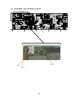
Page 75: ...8 3 8 3 ADJUSTMENT AND CHECKING LOCATION TFT LCD BOARD TOP A 05 2 1 3 4 5 VR801 TP8F2 VR803 ...
Page 76: ...8 4 E MEMO ...
Page 88: ...9 12 E MEMO ...


