8-1
SECTION 8
ELECTRICAL ADJUSTMENT
DVP-FX705
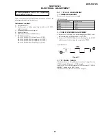
This section describes procedures and instructions necessary for
adjusting electrical circuits in this set.
Instruments required:
1) Color monitor TV
2) Oscilloscope 1 or 2 phenomena, band width over 100 MHz,
with delay mode
3) Frequency counter (over 8 digits)
4) Digital voltmeter
5) Standard commander (RMT-D163A)
6) DVD reference disc
HLX-501 (J-6090-071-A) (dual layer) (NTSC)
HLX-503 (J-6090-069-A) (single layer) (NTSC)
HLX-504 (J-6090-088-A) (single layer) (NTSC)
HLX-505 (J-6090-089-A) (dual layer) (NTSC)
8-1. TFT LCD ADJUSTMENT
1. POWER MEASURING
Measure each power after power supply
TFT-LCD Board
Measurement point
Specification
L807
–15V
L806
+17V
L810
+8.25V
2. VCOM WAVEFORM ADJUSTMENT
A. Adjust the VCOM Vpp level while changing the VR801 as be-
low waveform by using the scope in the TP8F2.
B. Adjust the VCOM DC Offset level while changing the VR803
as below waveform by using the scope in the TP8F2.
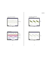
Vcom Waveform
Figure 8-1
3. TFT PANEL CHECK
Check that there is no big difference to color of image between
LCD Screen and TV monitor (LINE output).
And Use the “COLOR” adjustment (On LCD Screen) of “COLOR/
BRIGHT” button on the KEY Board.
Check the color depth of LCD screen is changed.
59.0
µ
s
4.6Vp-p
-0.8V
3.8V
GND
A
B
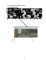
In making adjustment, refer to 8-3. Adjustment
and Checking Location.
Summary of Contents for DVP-FX705 - Portable Dvd Player
Page 4: ... 4 MEMO ...
Page 30: ...1 26 E MEMO ...
Page 34: ...2 4 E MEMO ...
Page 52: ...DVP FX705 4 28 E MEMO ...
Page 58: ...DVP FX705 5 12E MEMO ...
Page 62: ...DVP FX705 6 7 6 8 3 C Fig 8 3 C L403 MEMO ...
Page 72: ...7 8 E MEMO ...
Page 75: ...8 3 8 3 ADJUSTMENT AND CHECKING LOCATION TFT LCD BOARD TOP A 05 2 1 3 4 5 VR801 TP8F2 VR803 ...
Page 76: ...8 4 E MEMO ...
Page 88: ...9 12 E MEMO ...


