background image

DVP-NC60P

B

A

1

2

7

6

5

4

3

1-478-538-12

B

A

1

2

7

6

5

4

3

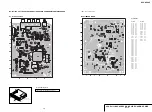
POWER BLOCK (SRV1487UC) PRINTED WIRING BOARD

POWER BOARD (SRV1487UC) (SIDE A)

For printed wiring board

There are a few cases that the part printed on
this diagram isn’t mounted in this model.

4-29

4-30

• 

 : Uses unleaded solder.

IF-127 board
(INTERFACE)

SW-443 board
(SWITCH)

Power board

FR-231 board
(FR)

MV-045 board
(CPU, Servo-DSP, AVDEC, 
DRIVE, VIDEO, AUDIO, POWER)

POWER BOARD (SRV1487UC) (SIDE B)

POWER BOARD

POWER BLOCK (SRV1487UC)

POWER BOARD
(SRV1487UC)

A SIDE

IC101

B-4

IC611

A-6

Q211

A-6

D101

A-4

D102

A-3

D103

A-3

D104

A-3

D105

B-4

D106

B-4

D107

A-4

D108

A-4

D211

A-5

D212

C-5

D213

A-6

D311

B-5

D312

B-5

D313

B-5

D315

A-6

D317

A-6

D318

A-7

D411

B-5

D511

C-5

B SIDE

Q311

A-1

Q611

A-2

Q712

A-1

Summary of Contents for DVP-NC60P - Cd/dvd Player

Page 1: ... 0 648 Vp p progressive or interlace 2 0 7 Vp p 75 ohms 1 BLACK LEVEL COMPONENT OUT is ON 2 BLACK LEVEL COMPONENT OUT is OFF LINE OUT VIDEO Phono jack 1 0 Vp p 75 ohms S VIDEO OUT 4 pin mini DIN Y 1 0 Vp p C 0 286 Vp p 75 ohms SPECIFICATIONS General Power requirements 120 V AC 60 Hz Power consumption 12 W Dimensions approx 430 83 410 mm 16 15 16 3 17 64 16 9 64 in width height depth incl projectin...

Page 2: ...urn to chassis must not exceed 0 5mA 500 microampers Leakage current can be measured by any one of three methods 1 A commercial leakage tester such as the Simpson 229 or RCA WT 540A Follow the manufacturers instructions to use these instruments 2 A battery operated AC milliammeter The Data Precision 245 digital multimeter is suitable for this job 3 Measuring the voltage drop across a resistor by m...

Page 3: ...ts 1 15 Using the Setup Display 1 15 Setting the Display or Sound Track Language LANGUAGE SETUP 1 15 Settings for the Display SCREEN SETUP 1 16 Custom Settings CUSTOM SETUP 1 16 Settings for the Sound AUDIO SETUP 1 16 Additional Information 1 17 Troubleshooting 1 17 Self diagnosis Function When letters numbers appear in the display 1 17 Glossary 1 17 Specifications 1 18 2 DISASSEMBLY 2 1 Disassemb...

Page 4: ...wer Supply Output Voltage Check 7 1 7 2 Adjustment of Video System 7 2 8 REPAIR PARTS LIST 8 1 Exploded Views 8 1 8 1 1 Main Section 8 1 8 1 2 Front Panel Section 8 3 8 1 3 Loading Section 8 4 8 1 4 Chassis Section 8 5 8 2 Electrical Parts List 8 6 ...

Page 5: ...d personnel before operating it any further On power sources The player is not disconnected from the AC power source as long as it is connected to the wall outlet even if the player itself has been turned off If you are not going to use the player for a long time be sure to disconnect the player from the wall outlet To disconnect the AC power cord grasp the plug itself never pull the cord On place...

Page 6: ... with identical region codes This system is used to protect copyrights DVD VIDEOs labeled will also play on this player If you try to play any other DVD VIDEO the message Playback prohibited by area limitations will appear on the TV screen Depending on the DVD VIDEO there may be no region code indication even though playing the DVD VIDEO is prohibited by area restrictions Format of discs DVD VIDEO...

Page 7: ...udio track number or JPEG image file number for DATA CDs DATA DVDs 3 Displays Super VCD as SVCD 4 Displays the date for JPEG files To turn off the display Press DISPLAY repeatedly Control Menu display 1 m Control Menu display 2 appears for certain discs only m Control Menu display off OFF 1 8 3 4 1 2 2 7 T 1 3 2 5 5 1 DVD VIDEO Quit PROGRAM ENTER DISPLAY SET ON OFF Currently playing title number 1...

Page 8: ... S VIDEO OUT LINE OUT COMPONENT VIDEO OUT R AUDIO L DIGITAL OUT COAXIAL OPTICAL VIDEO PR Y PB PB PR Audio video cord supplied Component video cord not supplied yellow TV projector or AV amplifier receiver to S VIDEO OUT TV projector or AV amplifier receiver S VIDEO cord not supplied TV projector or AV amplifier receiver red blue green blue red to LINE OUT VIDEO l Signal flow CD DVD player green ye...

Page 9: ...with the connected components S VIDEO OUT LINE OUT COMPONENT VIDEO OUT R AUDIO L DIGITAL OUT COAXIAL OPTICAL VIDEO PR Y PB VIDEO AUDIO INPUT L R B A LINE OUT R AUDIO L VIDEO DIGITAL OUT COAXIAL OPTICAL AV amplifier receiver with a decoder red TV projector or AV amplifier receiver Audio video cord supplied Signal flow Coaxial digital cord not supplied to DIGITAL OUT COAXIAL or OPTICAL to LINE OUT L...

Page 10: ...causing the speakers to be damaged DISC SKIP ENTER DISC SKIP With the playback side facing down Disc compartment number 25 Playing Discs Additional operations 1 DVD VIDEOs DVD RWs DVD Rs only 2 DVD VIDEOs DVD RWs DVD Rs DVD RWs only 3 Video and JPEG pictures only except BACKGROUND pictures You can move the enlarged picture using C X x c Depending upon the contents of the disc the zoom function may...

Page 11: ... VR Video Recording mode have two types of titles for playback originally recorded titles ORIGINAL and titles that can be created on recordable DVD players for editing PLAY LIST You can select the type of title to be played 1 Press DISPLAY when the player is in stop mode The Control Menu appears 2 Press X x to select ORIGINAL PLAY LIST then press ENTER The options for ORIGINAL PLAY LIST appear ENT...

Page 12: ...ct OFF in step 3 z Hints You can set Shuffle Play while the player is stopped After selecting the SHUFFLE option press H Shuffle Play starts Up to 200 chapters in a disc can be played in random order when CHAPTER is selected Notes You cannot use this function with VIDEO CDs or Super VCDs with PBC playback All Discs Repeat is automatically changed into One Disc Repeat when you set to shuffle play m...

Page 13: ...a starting point by inputting the time code ENTER DISPLAY CLEAR Number buttons 37 Searching for a Scene When playing a VIDEO CD or Super VCD without PBC Playback DISC TRACK INDEX When playing a VIDEO CD or Super VCD with PBC Playback DISC SCENE When playing a CD DISC TRACK When playing a DATA CD DATA DVD DISC ALBUM TRACK MP3 audio tracks only FILE JPEG image files only Example when you select CHAP...

Page 14: ... number are displayed after the text When playing VIDEO CDs with PBC functions the scene number or the playing time are displayed Long text that does not fit in a single line will scroll across the front panel display You can also check the time information and text using the Control Menu page 13 Notes Depending on the type of disc being played the DVD CD text or track name may not be displayed Th...

Page 15: ...S NIGHT function in the same way When the playing signal does not contain a signal for the rear speakers the surround effects cannot be heard When you select one of the TVS modes the player does not output the sound of center speaker Make sure that your listening position is between and at an equal distance from your speakers and that the speakers are located in similar surroundings The TVS effect...

Page 16: ...files that conform to the DCF image file format Design rule for Camera File system Image standards for digital cameras regulated by JEITA Japan Electronics and Information Technology Industries Association Notes The player will play any data with the extension MP3 JPG or JPEG even if they are not in MP3 or JPEG format Playing these data may generate a loud noise which could damage your speaker sys...

Page 17: ... direction 53 Enjoying MP3 Audio and JPEG Images Enjoying JPEG Images as a Slide Show You can play JPEG image files on a DATA CD or DATA DVD successively as a slide show 1 Press MENU The list of albums on the DATA CD DATA DVD appears 2 Press X x to select an album 3 Press H The JPEG images in the selected album start playing as a slide show To stop playback Press x Notes The slide show stops when ...

Page 18: ...ord enter the 6 digit number 199703 using the number buttons when the CUSTOM PARENTAL CONTROL display asks you for your password then press ENTER The display will ask you to enter a new 4 digit password Parental Control limited playback Playback of some DVD VIDEOs can be limited according to a predetermined level such as the age of the users The PARENTAL CONTROL function allows you to set a playba...

Page 19: ... the player is in stop mode The Control Menu appears 2 Press X x to select SETUP then press ENTER The options for SETUP appear 3 Press X x to select CUSTOM then press ENTER The Setup Display appears 4 Press X x to select the setup item from the displayed list LANGUAGE SETUP SCREEN SETUP CUSTOM SETUP or AUDIO SETUP Then press ENTER The Setup item is selected Example SCREEN SETUP 5 Press X x to sele...

Page 20: ...O settings in LANGUAGE SETUP page 62 If you set DTS to OFF page 66 the DTS sound track is not played even if you set TRACK SELECTION to AUTO If PCM DTS and Dolby Digital sound tracks have the same number of channels the player selects PCM DTS and Dolby Digital sound tracks in this order MULTI DISC RESUME DVD VIDEO VIDEO CD only Switches the Multi disc Resume setting on or off Resume playback can b...

Page 21: ...Shuffle Play Repeat Play or A B Repeat Play is selected page 30 Resume play has taken effect page 27 The player starts playing the disc automatically The disc features an auto playback function AUTO PLAY in CUSTOM SETUP is set to ON page 64 Playback stops automatically While playing discs with an auto pause signal the player stops playback at the auto pause signal Some functions such as Stop Searc...

Page 22: ...one frame the Progressive format shows the entire image at once as a single frame This means that while the Interlace format can show 30 frames 60 fields in one second the Progressive format can show 60 frames in one second The overall picture quality increases and still images text and horizontal lines appear sharper This player is compatible with the 480 progressive format Progressive JPEG Progr...

Page 23: ...Screw 3 Three Screws BV3 3 CR NOTE Follow the disassembly procedure in the numerical order given 2 2 UPPER CASE Loading Motor Ass y Page 2 5 Optical Pick Up Page 2 6 Rear Panel Section Page 2 2 Table Ass y Page 2 3 MV 045 Board Page 2 2 Front Panel Section Page 2 3 IF 127 Board Page 2 4 Power Block Page 2 7 FR 231 and SW 443 Boards Page 2 7 Upper Case Page 2 1 Set ...

Page 24: ... Flexible Cable CN107 23P 6 FIM 009 Flat Flexible Cable CN202 5P Pull the tray in the direction of the arrow B Insert a flat head screwdriver into a hole at the bottom the cam gear in the direction of the arrow A B A 5 MD 109 Harness CN201 6P MV 045 Board 3 Five Screws BV3 3 CR a a 2 1 Note Before remove FMO 006 Flat Flexible Cable please follow caution point at page 2 6 ...

Page 25: ...er 1 Four Screws BV3 3CR 2 PM 120 Harness CN201 10P 0 Mirror Reflector Assy 8 Cover Tray Assy 9 Screw BVT2 6 3CR 2 6 TABLE ASS Y Note If cover tray removed its should be replaced with new cover tray Two Screws BV3 3 CR 3 Front Panel Section 2 FIS 004 Flat Flexible Cable CN405 11P IF 127 PWB Connector CN201 1 Note Before remove FMO 006 Flat Flexible Cable please follow point at page 2 6 ...

Page 26: ...08 Flat Flexible Cable CN401 23P 5 FIM 009 Flat Flexible Cable CN403 5P 8 FIS 004 Flat Flexible Cable CN405 11P 9 FLD 3 Table Assy 2 Front Panel 0 IF 127 Board 2 7 IF 127 BOARD Note Caution Point on the PWB IF 127 When handling IF 127 PWB avoid contact with the sharp metal edge on the top side of Vacuum Fluorescent Display ND401 ...

Page 27: ...2 5 DVP NC60P Loading Motor Assembly M901 Table Belt Timing Screw M2 6x4 3CR Screw M2 6x4 3CR Claws Claw MD 105 Board ML 066 Harness CN004 2P 2 8 LOADING MOTOR ASS Y ...

Page 28: ...hort land before remove the harness from 24 pin BU connector Shortland Position Caution Point on the Laser Diode Laser Diode in the optical Device is very sensitive to Surge Current or ElectroStatic Discharge ESD After take out FMO 006 Flexible cable from CN101 of MV 045 board immediately ground FMO 006 Flexible cable pattern using short clip Metal paper clip can be used as short clip ...

Page 29: ...crew BVTP 2 6 3CR 2 FIS 004 flat flexible cable CN501 11P SW 443 board 4 FR 231 board 3 2 11 FR 231 AND SW 443 BOARDS 2 Two screws BV3 3 CR 3 Two claws Holder PS 4 Power block 1 PM 120 harness CN201 10P Power cord 2 10 POWER BLOCK ...

Page 30: ...8 DVP NC60P Optical pick up DEVICE OPTICAL KHM 310CAB C2RP Service assembly TD unit ass y PH101 on the SE 145 board PH102 on the SE 145 board Encoder ass y loading Loading motor ass y 2 12 INTERNAL VIEWS ...

Page 31: ...2 9 DVP NC60P IF 127 board INTERFACE SW 443 board SWITCH Power board FR 231 board FR MV 045 board CPU Servo DSP AVDEC DRIVE VIDEO AUDIO POWER 2 13 CIRCUIT BOARDS LOCATION ...

Page 32: ...2 10E DVP NC60P MEMO ...

Page 33: ... SW 10V SWITCHING REGULATOR RESET IC SPINDLE MOTOR SLED MOTOR M M M LOADING MOTOR CHUCK TRAY DETECT OPTICAL DEVICE DVD CD PDIC FOCUS COIL TRACKING COIL INLIMIT SENSOR Vkk EVER 3 3V IC403 TRAY DRIVER TRAY DETECT ROTATE M TURN TABLE SW443 BOARD SEE PAGE 3 13 to 3 14 LED 501 IC501 IR FUNCTION KEY FR231 BOARD SEE PAGE 3 13 to 3 14 POWER SWITCH MV 045 BOARD SEE PAGE 3 5 to 3 12 IF 124 BOARD SEE PAGE 3 ...

Page 34: ...C403 Audio Buffer IC401 Motor Driver IC201 CN107 11 CN101 IC405 Optical Out Audio DAC IC406 Coaxial Q411 RESET IC IC108 FLASH ROM IC102 EEPROM IC103 SDRAM IC104 1 8V Reg IC110 3 3V Reg IC 105 7 5V Reg IC303 Video Buffer IC304 MTK IC IC101 VCC OPTICAL DEVICE EVER 5V POWER EVER 10V SW 5V SW 3 3V EVER 5V EVER 11V AU 11V SW 8V CN501 CN201 Q611 L421 D411 D211 2 Line fiters Switching IC Circuit Bridge R...

Page 35: ...K MAMUTE C V MUTE Y V Y G CB B CR R WIDE 196 194 198 200 202 203 209 ASDATA4 222 ASDATA4 C Y CVBS Y G CB B CR R WIDE 229 228 XTALI XTALO XRST 102 103 6 5 IC103 EEPROM SCL SDA IC101 C BAR PB 5 IC101 C BAR PB 6 IC101 7 IC101 8 202 203 200 198 199 196 IC101 C BAR PB 4 IC101 C BAR PB 3 IC 108 RESET IC CN 107 1 MV 045 BOARD SEE PAGE 4 7 to 4 8 TO MV 045 AUDIO SEE PAGE 3 9 TO MV 045 VIDEO SEE PAGE 3 11 ...

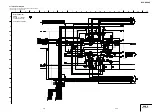
Page 36: ... MUTE123 PS IC201 FAN8036L MOTOR DRIVER IC IC101 CXD9849R RF AMPLIFIER LDM LDM OKSW1 OCSW1 FCS FCS TRK TRK LD 780 LD 650 PD RF F E LOADING MOTOR CHUCK TRAY DETECT MS 203 BOARD FOCUS COIL TRACKING COIL DVD CD LD MODULE 1 2 5 6 3 CN202 5 4 2 1 DVD CD LD DRIVE Q102 2 5 8 11 24 23 22 21 6 2 5 14 10 17 20 C D A B 19 16 15 CN101 DVD CD PDIC 178 174 170 47 39 37 38 41 42 16 FWD 17 REV 35 MV 045 BOARD SEE...

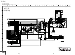
Page 37: ...VER Q402 Q404 Q405 AOUTR MCLK SDTI PDN CSN BICK LRCK CCLK CDTI DZFR DZFL MAMUTE AOUTR AOUTL AOUTL AUDIO AMPLIFIER AUDIO D A CONVERTER LINE OUT Q411 BUFFER R435 J301 OPTICAL IC405 COAXIAL A MUTE D IN 1 11 12 10 9 Q408 MUTE 2 3 5 6 1 7 Q407 MUTE 1 3 3Vp p 40 71ns IC406 1 DVD 13 3 3Vp p 44 24ns IC406 1 CD 12 SYSTEM CONTROL SEE PAGE 3 5 to 3 6 ACLK ALRCK ABCK XDACS ASDATA4 XRST ADSK ADSOO ...

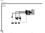
Page 38: ...Y OUT Y IN C IN C OUT MUTE2 Y IN Y OUT Y Cb Cr Cb IN Cr IN Cb OUT Cr OUT VIDEO COMBO JACK J301 2 5Vp p 63 5usec IC304 wl 15 1 8Vp p IC304 ea 19 2 0Vp p IC304 wg 16 1 4Vp p IC304 wa 18 1 4Vp p IC304 wd 17 2 0Vp p IC304 wj 14 VIDEO BUFFER IC304 MV 045 BOARD SEE PAGE 4 11 to 4 12 SYSTEM CONTROL SEE PAGE 3 5 to 3 6 63 5usec 63 5usec 63 5usec 63 5usec 63 5usec ...

Page 39: ... 41 SACD LED MULTI LED KEY OPEN CLOSE PROG LED IC 404 IF CON SYSAST CS SI SO SC AMUTE VMUTE BUSY PCONT CN 401 CN 405 SYSRST XIFCS SOO SIO SCO A MUTE V MUTE XIFBUSY PCONT CN 501 CN 601 S601 POWER IC403 2 3 XIN XOUT X401 8MHZ 1 IC 501 S510 S511 S512 S513 S514 S508 STOP PROG 4 3 2 1 S509 S510 S511 S505 S504 S503 S502 R504 R505 R506 R507 S501 D501 CN 502 OPEN CLOSE EXCHANGE PROG SEL R512 PLAY PAUSE PR...

Page 40: ...SP 2 LIMIT 3 SL 5 SL 6 GND LIMIT 4 TO JIG 1 695 320 91 HARNESS 1 5mm 2 OCSW1 3 CKSW1 4 GND 5 SENSOR LED 1 NC 2 SACD 3 MULTI_LED 4 POWER 5 DVD_AUDIO 6 GND 6 5 4 3 2 1 6 TM 5 TM 4 SGND 3 DSENS 2 TSENSD 1 SENSOR LED 1 TM 2 TM 2P CN102 CN101 6P CN002 6P 6 TSENS 3P CN003 D5045 6P CN601 2P CN004 1 SGND 6P CN204 TO JIG 6 RF MON 5 V2REFO 1 OCSW1 REV CN202 5P 2 CKSW1 FWD 3 GND CTL OCSW1 REV 5 CKSW1 FWD 4 G...

Page 41: ...ern face side seen from Side A the pattern face are indicated Parts face side Parts on the parts face side seen from Side B the parts face are indicated When indicating parts by reference number please include the board name Note The components identi fied by mark or dotted line with mark are criti cal for safety Replace only with part number specified Note Les composants identifiés par une marque...

Page 42: ...B A 1 2 5 4 3 CPU Servo DSP AVDEC DRIVE VIDEO AUDIO POWER MV 045 MV 045BOARD A SIDE IC101 C 4 IC102 B 3 IC103 B 4 IC104 C 5 IC108 A 2 IC110 D 2 IC201 B 2 IC401 E 4 IC402 E 4 IC404 G 5 IC405 G 4 IC406 E 4 Q101 C 4 Q102 D 2 Q103 C 4 Q304 F 3 Q305 F 2 Q307 F 4 Q371 F 1 Q372 F 1 Q373 E 1 Q374 F 1 Q401 E 3 Q402 E 5 Q403 E 3 Q404 E 4 Q405 F 4 Q406 E 5 Q409 E 5 Q410 F 5 Q414 F 3 Q417 F 2 Q501 E 1 Q502 E ...

Page 43: ... DVP NC60P 4 7 4 8 CPU Servo DSP AVDEC MV 045 1 5 For Schematic Diagram Refer to page 4 5 for printed wiring board of MV 045 board Refer to page 4 4 for waveform MV 045 BOARD 1 5 CPU Servo DSP AVDEC REF NO 1000 SERIES XX MARK NO MOUNT NO MARK REC PB MODE XX ...

Page 44: ...7 6 5 4 3 14 15 DVP NC60P 4 10 DRIVE MV 045 2 5 4 9 For Schematic Diagram Refer to page 4 5 for printed wiring board of MV 045 board Refer to page 4 4 for waveform MV 045 BOARD 2 5 DRIVE REF NO 1000 SERIES XX MARK NO MOUNT NO MARK REC PB MODE ...

Page 45: ... 4 12 VIDEO MV 045 3 5 For Schematic Diagram Refer to page 4 5 for printed wiring board of MV 045 board Refer to page 4 4 for waveform MV 045 BOARD 3 5 VIDEO REF NO 1000 SERIES XX MARK NO MOUNT NO MARK REC PB MODE SIGNAL PATH VIDEO SIGNAL CHROMA PB Y Y CHROMA AUDIO SIGNAL ...

Page 46: ... 4 14 MV 045 BOARD 4 5 AUDIO REF NO 1000 SERIES XX MARK NO MOUNT NO MARK REC PB MODE For Schematic Diagram Refer to page 4 5 for printed wiring board of MV 045 board Refer to page 4 4 for waveform AUDIO MV 045 4 5 SIGNAL PATH VIDEO SIGNAL CHROMA PB Y Y CHROMA AUDIO SIGNAL ...

Page 47: ...ard Refer to page 4 4 for waveform MV 045 BOARD 5 5 POWER REF NO 1000 SERIES XX MARK NO MOUNT NO MARK REC PB MODE The components identified by mark or dotted line with mark are critical for safety Replace only with part number specified Les composants identifiés par une marque sont critiques pour la sécurité Ne les remplacer que par une pièce portant le numéro spécifié ...

Page 48: ...C474 A 9 Q401 B 7 Q402 B 7 Q403 B 6 Q405 A 9 Q406 B 7 Q407 B 7 Q408 B 6 Q409 B 7 Q410 B 7 Q411 B 6 D402 A 8 D403 C 7 D404 B 7 D405 B 7 D406 C 8 D412 B 6 There are a few cases that the part printed on this diagram isn t mounted in this model For printed wiring board IF 127 board INTERFACE SW 443 board SWITCH Power board FR 231 board FR MV 045 board CPU Servo DSP AVDEC DRIVE VIDEO AUDIO POWER A 1 2 ...

Page 49: ...10 9 8 7 6 5 4 3 14 15 DVP NC60P 4 19 4 20 For Schematic Diagram Refer to page 4 17 for printed wiring board of IF 127 board IF 127 BOARD INTERFACE REF NO 1000 SERIES XX MARK NO MOUNT NO MARK PB MODE MARKED MOUNT TABLE INTERFACE IF 127 ...

Page 50: ... Uses unleaded solder SWITCH SW 443 SW 443 BOARD B SIDE SW 443BOARD A SIDE IC501 B 1 D501 B 1 There are a few cases that the part printed on this diagram isn t mounted in this model For printed wiring board IF 127 board INTERFACE SW 443 board SWITCH Power board FR 231 board FR MV 045 board CPU Servo DSP AVDEC DRIVE VIDEO AUDIO POWER ...

Page 51: ...11 10 9 8 7 6 5 4 3 14 15 DVP NC60P 4 23 4 24 For Schematic Diagram Refer to page 4 21 for printed wiring board of SW 443 board SW 443 BOARD SWITCH REF NO 1000 SERIES XX MARK NO MOUNT NO MARK PB MODE MARKED MOUNT TABLE SWITCH SW 443 ...

Page 52: ... a few cases that the part printed on this diagram isn t mounted in this model For printed wiring board IF 127 board INTERFACE SW 443 board SWITCH Power board FR 231 board FR MV 045 board CPU Servo DSP AVDEC DRIVE VIDEO AUDIO POWER A 1 2 5 4 3 FR 231 BOARD B SIDE A 1 2 5 4 3 FR 231BOARD A SIDE D602 A 3 D603 A 4 ...

Page 53: ... 13 11 10 9 8 7 6 5 4 3 14 15 DVP NC60P 4 27 4 28 For Schematic Diagram Refer to page 4 25 for printed wiring board of FR 231 board FR 231 BOARD FR REF NO 1000 SERIES XX MARK NO MOUNT NO MARK PB MODE MARKED MOUNT TABLE FR FR 231 ...

Page 54: ...aded solder IF 127 board INTERFACE SW 443 board SWITCH Power board FR 231 board FR MV 045 board CPU Servo DSP AVDEC DRIVE VIDEO AUDIO POWER POWER BOARD SRV1487UC SIDE B POWER BOARD POWER BLOCK SRV1487UC POWERBOARD SRV1487UC A SIDE IC101 B 4 IC611 A 6 Q211 A 6 D101 A 4 D102 A 3 D103 A 3 D104 A 3 D105 B 4 D106 B 4 D107 A 4 D108 A 4 D211 A 5 D212 C 5 D213 A 6 D311 B 5 D312 B 5 D313 B 5 D315 A 6 D317 ...

Page 55: ... SRV1487UC REF NO 1000 SERIES XX MARK NO MOUNT NO MARK PB MODE MARKED MOUNT TABLE The components identified by mark or dotted line with mark are critical for safety Replace only with part number specified Les composants identifiés par une marque sont critiques pour la sécurité Ne les remplacer que par une pièce portant le numéro spécifié 4 31 4 32E POWER BOARD POWER BLOCK SRV1487UC ...

Page 56: ...r monitor input 21 MDI2 Analog Input Laser power monitor input 22 LDO2 Analog Output Laser driver output 23 LDO1 Analog Output Laser driver output 24 SVDD3 Power Analog 3 3V power 25 CSO Analog Output Central servo 26 RFLVL Analog Output RFRP low pass output 27 SGND Ground Ground pin for analog circuitry 28 V2REFO Analog Output Reference voltage 2 8V 29 V20 Analog Output Reference voltage 2 0V 30 ...

Page 57: ...ower 3 3V power pin for internal digital circuitry 74 HA10 Output PU Host address bit10 75 HA9 Output PU Host address bit9 76 HA20 Output SMT Host address bit20 77 xROMCS Output PU SMT Chip select active Low 78 HA1 Output PU Host address bit1 79 xRD Output SMT Read enable active Low 80 DVDD3 Power 3 3V power pin for internal digital circuitry 81 HD0 Output Host data bit0 82 HD1 Output Host data bi...

Page 58: ...4 121 RD3 Output DRAM data bti3 122 DVDD18 Power 1 8V power pin for internal digital circuitry 123 RD2 Output DRAM data bit2 124 RD1 Output DRAM data bit1 125 RD0 Output DRAM data bit0 126 RD15 Output DRAM data bit15 127 DVDD3 Power 3 3V power pin for internal digital circuitry 128 RD14 Output DRAM data bit14 129 RD13 Output DRAM data bit13 130 RD12 Output DRAM data bit12 131 RD11 Output DRAM data...

Page 59: ... used 172 Not used 173 DVDD18 Power 1 8V power pin for internal digital circuitry Output Default 174 MUTE Output PD Servo GPIO 4 175 Not used 176 XMAMUTE Default LOW Main Audio Mute Signal H Unmute L Mute 177 DSEL Output Interlace Prog select output signal H 480i L 480P 178 TSD_M Input PU SERVO GPIO 3 179 EUROVY Output PU CVBS S terminal select output signal H CBVS L S Terminal 180 Not used 181 No...

Page 60: ...o serial data 4 Down mixed L R 223 DVSS Ground Ground pin for internal digital circuitry 224 D WIDE Input Video aspect ratio control for D terminal H 16 9 L 4 3 225 SPDIF Output SPDIF output 226 RFGND18 Ground Ground pin for internal analog circuitry 227 RFVDD18 Power 1 8V power pin for internal analog circuitry 228 XTALO Output 27M crystal output 229 XTALI Input 27M crystal input 230 JITFO Analog...

Page 61: ...1 Not used 252 OSP Analog Output RF Offset cancellation capacitor connecting 253 OSN Analog Output RF Offset cancellation capacitor connecting 254 RFGC Analog Output RF AGC loop capacitor conecting for DVD ROM 255 IREF Analog Input Current reference input 256 AVDD3 Power 3 3V power pin for analog circuirtry 5 6E ...

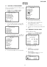
Page 62: ...us menu 4 Select Iop by pressing 6 key on the remote commander 5 Wait until a hexadecimal number appear Manual Adjust 1 Track Balance Adjust 2 Track Gain Adjust 3 Focus Balance Adjust 4 Focus Gain Adjust 5 Eq Boost Adjust 6 Iop ED 7 TRV Level 8 S curve FE Level 9 RFL PI Level 0 MIRR Time Change Value Return to previous menu 6 Convert data from hexadecimal to decimal 7 Use the following formula to ...

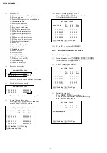
Page 63: ...urs Press DISPLAY CLEAR keys in this order Both CD and DVD data are cleared Emg History Check Laser Hours CD 0h 0min DVD 0h 0min 1 01 05 04 04 00 92 46 00 00 00 00 00 00 00 23 45 2 02 02 01 01 00 A9 4B 00 00 00 00 00 00 00 23 45 Next Next Page Prev Prev Page Return to Top Menu 10 How to Clearing Emergency code Press TOPMENU CLEAR keys in this order All emergency code are cleared Emg History Check ...

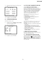
Page 64: ...M CONTROL In the test mode the following functions can be checked 1 Button function 2 Remote commander receiving function 3 SYSTEM CONTROL IF CON serial communication 4 Click shuttle function 5 Fluorescent display tube lighting check Grid check Anode check In the test mode the main unit operates same as usual except voltage monitoring communication display of fluorescent display tube 1 The routine...

Page 65: ...f Check mode becomes active at the AC Power ON or by key input the test display of the following steps 1 to 4 is repeated 1 FLD and LED all ON for 5 seconds 2 MODEL display for 2 seconds 3 Version display for 2 seconds 4 ROM creation date display for 2 seconds ...

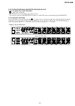
Page 66: ... on the main unit except keys transited in Self Check Mode 2 3 2 2 Operation and Display When a key on the main unit is pressed in the Self Check mode key code is displayed on the FLD Key code display at input of H key key code 0Ah At input of faulty voltage 1 2 3 4 5 DVD VCD MP3 ALL DISCS 1 2 3 4 5 DVD VCD MP3 ALL DISCS 1 2 3 4 5 DVD VCD MP3 ALL DISCS Input Voltage V IC404 Pin No Signal PIN ef AD...

Page 67: ...mote commander during Anode Test display This unit does not provide JOG SHUTTLE and therefore use another DVD remote commander having the JOG SHUTTLE 2 3 4 2 Operation and Display The Self Check Mode transits to this mode when t key is entered This tests whether each segment turns on individually Only the first segment of each grid of FLD turns on and each time the SHUTTLE is entered the segment o...

Page 68: ...E 2 3 5 2 Operation and Display The Self Check Mode transits to this mode when R key is entered This tests whether each grid turns on individually The first grid only of FLD turns on and other grid turn off Each time the SHUTTLE is entered the grid is switched in order When SHUTTLE input is clockwise the grid switched in 1 2 3 direction or counterclockwise it switches in 3 2 1 direction Display at...

Page 69: ... m f b h j k a p r d _ _ _ _ _ Dp 3G n e c g s m f b h j k a p r d col _ _ _ _ Dp 4G n e c g s m f b h j k a p r d _ _ _ _ _ Dp 5G n e c g s m f b h j k a p r d col _ _ _ _ Dp 6G n e c g s m f b h j k a p r d _ _ _ _ _ Dp 7G n e c g s m f b h j k a p r d _ Dp 8G e c g f b a d 1 2 3 4 5 D V D V C D M P 3 A L L D I S C S 1 2 3 4 5 D V D V C D M P 3 A L L D I S C S e r p n d c f b h s j k m a 3G 5G 2...

Page 70: ... HLX 505 J 6090 089 A dual layer NTSC 7 1 POWER SUPPLY OUTPUT VOLTAGE CHECK Mode Except standby Instrument Digital multimeter EVER 5 V Check Test point CN201 pin 4 Specification 5 0 0 3 Vdc SW 3 3 V Check Test point CN201 pin 5 Specification 3 35 0 2 Vdc SW 5 V Check Test point CN201 pin 6 Specification 5 0 Vdc SW 8 V Check Test point CN201 pin 1 Specification 8 0 0 5 Vdc EVER 11 V Check Test poin...

Page 71: ... In theVideo Signal menu 1 Color Bar 100 play back 2 Confirm that theY level is 1 0 0 08 Vp p Fig 7 2 3 Checking SVideo Output S Y Purpose Check S terminal video output If it is incorrect pictures will not be displayed correctly in spite of connection to the TV with a S terminal cable Mode HLX 504 Signal Color bars 100 Test point S VIDEO OUT S Y connector 75 Ω terminated Instrument Oscilloscope Sp...

Page 72: ...rect correct colors will not be displayed when connected to for instance projector Mode HLX 504 Signal Color bars Test point COMPONENT VIDEO OUT PB connector 75 Ω terminated Instrument Oscilloscope Specification A 700 70 mVp p Checking method 1 In theVideo Signal menu 1 Color Bar 100 play back 2 Confirm that the B Y level is A Fig 7 6 7 Checking ComponentVideo Output R Y Purpose This checks compon...

Page 73: ...7 4E DVP NC60P MEMO ...

Page 74: ... anticipated when ordering these items The mechanical parts with no reference number in the exploded views are not supplied Color Indication of Appearance Parts Example KNOB BALANCE WHITE RED R R Parts Color Cabinet s Color 8 1 EXPLODED VIEWS DVP NC60P 8 1 1 MAIN SECTION ns not supplied a b c b Loading section ns a c 2 qa 9 Front panel section ns qj d g g e f d e f qs qf qg 4 7 8 q qh 9 9 9 5 7 6 ...

Page 75: ...1 A MV 045 1940 U2 COMPL 2 1 478 538 12 POWER SUPPLY BLOCK 4 3 091 487 31 TRAY 5 X 2050 481 1 UPPER CASE 6 1 828 451 21 POWER SUPPLY CORD 7 3 070 883 41 SCREW TAPPING 8 3 077 331 11 BV3 3 CR 9 3 077 331 21 BV3 3 CR 10 1 479 179 41 REMOTE COMMANDER RMT D176A 11 3 957 819 01 FOOT 12 1 828 878 11 FFC FIS 004 13 1 830 273 11 FLEXIBLE FLAT CABLE FIM 008 14 1 830 274 11 FLEXIBLE FLAT CABLE FIM 009 15 1 ...

Page 76: ......

Page 77: ...24 A LOADING ASSY T 100 X 2025 232 2 COVER ASSY TRAY P S 102 3 087 053 01 BVTP 2 6 3CR 103 3 088 617 01 SCREW P M3 X M3 3CR 104 3 016 533 01 WASHER FR STOPPER 105 3 074 725 01 BELT TD 106 A 1107 526 A UNIT ASSY TD 107 3 074 737 21 PLATE GUIDE 108 X 3954 419 2 MIRROR ASSY REFLECTOR 109 A 1107 525 A TABLE ASSY Ref No Part No Description Remark ...

Page 78: ......

Page 79: ... 1 163 021 91 CERAMICCHIP 0 01UF 10 00 50V C407 1 115 339 11 CERAMICCHIP 0 1UF 10 00 50V C408 1 115 339 11 CERAMICCHIP 0 1UF 10 00 50V C409 1 115 339 11 CERAMICCHIP 0 1UF 10 00 50V C417 1 130 481 00 MYLAR 0 0068UF 5 00 50V C418 1 115 339 11 CERAMICCHIP 0 1UF 10 00 50V C419 1 104 666 11 ELECT 220UF 20 00 25V C420 1 163 021 91 CERAMICCHIP 0 01UF 10 00 50V C422 1 115 339 11 CERAMICCHIP 0 1UF 10 00 50...

Page 80: ...5 1 10W R445 1 216 025 11 RES CHIP 100 5 1 10W R446 1 216 025 11 RES CHIP 100 5 1 10W R447 1 216 025 11 RES CHIP 100 5 1 10W R448 1 216 025 11 RES CHIP 100 5 1 10W R449 1 216 089 91 RES CHIP 47K 5 1 10W R450 1 216 089 91 RES CHIP 47K 5 1 10W R451 1 216 073 91 RES CHIP 10K 5 1 10W R452 1 216 073 91 RES CHIP 10K 5 1 10W R453 1 216 073 91 RES CHIP 10K 5 1 10W R454 1 216 049 11 RES CHIP 1K 5 1 10W R46...

Page 81: ... 970 11 CERAMICCHIP 0 01UF 10 00 25V C205 1 164 230 11 CERAMICCHIP 220PF 5 00 50V C206 1 164 230 11 CERAMICCHIP 220PF 5 00 50V C208 1 162 970 11 CERAMICCHIP 0 01UF 10 00 25V C209 1 164 677 11 CERAMICCHIP 0 033UF 10 00 16V C210 1 162 970 11 CERAMICCHIP 0 01UF 10 00 25V C211 1 164 677 11 CERAMICCHIP 0 033UF 10 00 16V C212 1 162 970 11 CERAMICCHIP 0 01UF 10 00 25V C213 1 162 970 11 CERAMICCHIP 0 01UF...

Page 82: ...ISTOR Q101 6 550 008 01 TRANSISTORUM6K1N TN Q102 6 550 653 01 TRANSISTORQST8TR Q103 8 729 424 59 TRANSISTORUN2212 TX Q304 8 729 024 89 TRANSISTORMUN2213T1 Q305 8 729 024 83 TRANSISTORMUN2111T1 Q401 8 729 010 08 TRANSISTORMSB710 RT1 Q402 8 729 024 89 TRANSISTORMUN2213T1 Q403 8 729 010 25 TRANSISTORMSD601 RT1 Q404 8 729 424 70 TRANSISTORUN2217 QRS TX Q405 8 729 010 05 TRANSISTORMSB709 RT1 Q407 6 551...

Page 83: ...48 1 216 864 11 SHORTCHIP 0 R249 1 216 864 11 SHORTCHIP 0 R250 1 216 864 11 SHORTCHIP 0 R251 1 216 864 11 SHORTCHIP 0 R320 1 216 864 11 SHORTCHIP 0 R321 1 216 833 11 METAL CHIP 10K 5 1 10W R325 1 216 864 11 SHORTCHIP 0 R327 1 216 833 11 METAL CHIP 10K 5 1 10W R331 1 211 990 11 METAL CHIP 75 0 5 1 10W R332 1 211 990 11 METAL CHIP 75 0 5 1 10W R333 1 211 990 11 METAL CHIP 75 0 5 1 10W R334 1 211 990...

Page 84: ...05X4 RB107 1 234 371 21 RES NETWORK 47 1005X4 RB108 1 234 371 21 RES NETWORK 47 1005X4 RB109 1 234 371 21 RES NETWORK 47 1005X4 RB110 1 234 371 21 RES NETWORK 47 1005X4 RB111 1 234 371 21 RES NETWORK 47 1005X4 RB112 1 234 371 21 RES NETWORK 47 1005X4 RB113 1 234 371 21 RES NETWORK 47 1005X4 RB114 1 234 371 21 RES NETWORK 47 1005X4 RB115 1 234 371 21 RES NETWORK 47 1005X4 CYRSTAL X102 1 813 539 11 ...

Page 85: ... 771 410 21 SWITCH TACT 1 478 538 12 POWERBLOCK SRV1487UC ACCESSORIES 1 751 271 71 CORD CONNECTION AV 2 585 637 11 MANUAL INSTRUCTION ENGLISH 2 585 637 21 MANUAL INSTRUCTION FRENCH CND 1 479 179 41 REMOTECOMMANDER RMT D176A POWER BLOCK SRV1487UC Note The components identified by mark or dotted line with mark are critical for safety Replace only with part number specified SW 443 ...

Page 86: ...8 13E DVP NC60P 109 Sony Corporation Home Electronics Network Company 2005C0800 1 2005 03 Published by Product Design 1 Department 9 874 859 11 ...

Reviews: