6-18
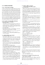
6-11. TROUBLESHOOTING
6-11-1. Cannot Enter Test Mode
You cannot enter the Test mode when either button has been pressed
by any reason with the board assembled in the front panel. In this
state, the power does not turn on even under normal condition (the
set is kept in standby state), and also no button is active and the
remote commander is not accepted. In this case, disconnect the
MB-100 board and AV-58 board, and with the SELF CHECK (
0
pin) of IF CON (IC404) on the IF-83 board kept in low state, sup-
ply AC, and the Test mode will be forcibly activated. Or, on the
board, short the land printed as “SELF” to enter the Test mode.
The IF CON (IC404) checks the SELF CHECK port only after the
power on reset (only at AC supply, not in standby state). If any
button is pressed, its name is displayed on the fluorescent display
tube. But, if other than “NOTHING” is displayed though no but-
ton is pressed, it means that any button has been pressed.
6-11-2. Faults in Test Mode (MB-100 Board)
1. Test mode menu is not displayed
• Board visual check
Check main IC’s, SYSTEM CONTROL (IC103), ROM (IC107
or IC108), AVD (IC503), and ARP&SERVO (IC302), for mount-
ing condition, direction, or evidence of short between pins, or
soldering failure. Also, compare with good board to check if
there are missing capacitors or resistors.
• Clock signal check
Measure the clock frequency at CPUCK (
uj
pin) of the SYS-
TEM CONTROL (IC103) using an oscilloscope.
If 33 MHz is outputted, an access to the ROM is normal, and
then check the items in 1-2.
In the case of 8.25 MHz output, check the items in 1-1.
If it is fixed to “H” or “L”, the X101 or SYSTEM CONTROL
(IC103) will be faulty.
1-1. CPUCK (33 MHz) is not outputted
• Power supply voltage check
Check the power connectors of the boards or power input pins
of the IC’s for voltage. Check the IC’s in order of SYSTEM
CONTROL (IC103), ROM (IC107 or IC108), AVD (IC503), and
ARP&SERVO (IC302). If correct voltage is not outputted, the
power line will be shorted, or soldering or IC will be faulty.
• Reset signal check
Check that the XFRRST (
uh
pin) of SYSTEM CONTROL
(IC103) is “H” (3.3 V). If not “H”, a soldering failure of that
line, a shot with other line, or faulty SYSTEM CONTROL
(IC103) is doubtful.
• XRD, XWRH, and CS0X signals check
Using an oscilloscope, measure the XRD (
u;
pin), XWRH (
ua
pin) of the SYSTEM CONTROL (IC103)
to check if they are fixed to “L” (0 V) or “H” (3.3 V), or if they
are on the intermediate potential between “L” and “H”. If they
are fixed to “L” or “H”, or on the intermediate potential, a sol-
dering failure of that line, a shot with other line, or faulty SYS-
TEM CONTROL (IC103) is doubtful.
• HA [0 – 21] and HD [0 – 15] signals check
Using an oscilloscope, measure the HA [0
–
21] (
<z/x>
–
<z/.>
,
<zzz>
–
<zz,>
,
<zx/>
,
1
–
5
pins) and HD [0
–
15] (
ig
–
<z//>
pins) of the
SYSTEM CONTROL (IC103) to check if they are fixed to “L”
(0 V) or “H” (3.3 V), or if HA is on the intermediate potential
between “L” and “H” (HD is on intermediate potential in nor-
mal state), or if same waveform as that of adjacent pins is mea-
sured. In case of “L” or “H”, intermediate potential, or same
waveform, a soldering failure of that line, a shot with other line,
or faulty SYSTEM CONTROL (IC103) is doubtful.
1-2. CPUCK (33 MHz) is outputted
(communication with ROM is normal)
• AVD (IC503) check
Using an oscilloscope, measure the SDCLKO (
<zv.>
pin) of the
AVD (IC503) to check that 95 MHz is outputted. If not output-
ted, a short of 27 MHz line across CLKI (
<z,/>
pin) and SCLKIN
(
<z,x>
pin), IC mounting failure, or faulty AVD (IC503) is doubt-
ful. If 27 MHz is outputted, the communication between SYS-
TEM CONTROL (IC103) and AVD (IC503) is disabled, and
therefore check the following items, particularly the AVD
(IC503).
• WAIT signal check
Using an oscilloscope, measure the XWAIT (
yj
pin) of the SYS-
TEM CONTROL (IC103) to check if it is fixed to “L” (0 V) or
on the intermediate potential. In case of “L” or intermediate
potential, examine CS2X
–
CS5X (
y;
–
yd
pins) to check if any
pin is fixed to “L”.
For the CS2X and CS3X, AVD (IC503) mounting failure or faulty
IC is doubtful.
For the CS4X and CS5X, ARP&SERVO (IC302) mounting fail-
ure or faulty IC is doubtful.
If CS2X
–
CS5X are not “L”, or they are sometimes on interme-
diate potential, a soldering failure of XWAIT line, a short with
other line, or faulty SYSTEM CONTROL (IC103) is doubtful.
• INT signal check
Using an oscilloscope, measure the INT0
–
2, 4
–
6 (
qh
–
qk
pins,
w;
–
ws
pins) of the SYSTEM CONTROL (IC103) to check
if INT0
–
2, and 6 are fixed to “L” (0 V) and INT5 is fixed to
“H” (3.3 V), or they are on intermediate potential. In case of
“L”, “H”, or intermediate potential, a soldering failure of IC’s
connected to that line, a short with other line, faulty SYSTEM
CONTROL (IC103), or faulty each IC is doubtful.
INT0
: AVD (IC503)
INT1, INT2 : ARP&SERVO (IC302)
INT5, INT6 : AUDIO DSP (IC701)
• CSnX signals check
Using an oscilloscope, measure the CX0X
–
CX7X (
tk
–
yd
,
yg
,
yh
pins) of the SYSTEM CONTROL (IC103) to check if
they are fixed to “L” (0 V), or two or more CS’s sometime go
“L”, or on intermediate potential. In case of fixed “L”, two or
more CS’s on “L” or intermediate potential, a soldering failure
of IC’s connected to that line, a short with other line, faulty
SYSTEM CONTROL (IC103), or faulty each IC is doubtful.
CS0X
: ROM (IC107 or IC108)
CS2X, CS3X: AVD (IC503)
CS4X, CS5X: ARP&SERVO (IC302)
• Other CS signals check
Using an oscilloscope, measure the VESCS/X39CS (
i;
pin) and
XDACS (
ul
pin) of the SYSTEM CONTROL (IC103) to check
if they are fixed to “L”. If fixed, a soldering failure of that line,
a short with other line, or faulty SYSTEM CONTROL (IC103)
is doubtful.
If the above checking could not find a fault, check the outputted
CS signal. If CS signal other than CS0X is outputted, a mounting
failure of each IC or faulty IC that corresponds to active CS signal
is doubtful.
CS2X, CS3X: AVD (IC503)
CS4X, CS5X: ARP&SERVO (IC302)
2. Test mode menu is displayed, but operation stops
when a menu is selected
Using an oscilloscope, measure the PLCKO (
og
pin) of the ARP&
SERVO (IC302) to check if it is fixed to “L” (0 V) or “H” (3.3 V).
If fixed to “L” or “H”, the ARP&SERVO (IC302) is faulty. If not
fixed, check the items in 1-2. in order.
www. xiaoyu163. com
QQ 376315150
9
9
2
8
9
4
2
9
8
TEL 13942296513
9
9
2
8
9
4
2
9
8
0
5
1
5
1
3
6
7
3
Q
Q
TEL 13942296513 QQ 376315150 892498299
TEL 13942296513 QQ 376315150 892498299


