background image

– 2 –

WARNING!!

WHEN  SERVICING,  DO  NOT  APPROACH  THE  LASER
EXIT  WITH  THE  EYE  TOO  CLOSEL
Y.  IN  CASE  IT  IS
NECESSARY  TO  CONFIRM  LASER  BEAM  EMISSION,
BE  SURE  TO  OBSERVE  FROM  A  DIST
ANCE  OF
MORE   THAN   25  cm  FROM  THE  SURF
ACE  OF  THE
OBJECTIVE  LENS  ON  THE  OPTICAL  PICK-UP  BLOCK.

CAUTION

Use of controls or adjustments or performance of procedures
other than those specified herein may result in hazardous ra-
diation exposure.

ATTENTION  AU  COMPOSANT  AYANT  RAPPORT

À  LA  SÉCURITÉ!

LES  COMPOSANTS  IDENTIFIÉS  PAR  UNE  MARQUE  

0

SUR  LES  DIAGRAMMES  SCHÉMATIQUES  ET  LA  LISTE
DES  PIÈCES  SONT  CRITIQUES  POUR  LA  SÉCURITÉ
DE  FONCTIONNEMENT.  NE  REMPLACER  CES  COM-
POSANTS  QUE  PAR  DES  PIÈCES  SONY  DONT  LES
NUMÉROS  SONT  DONNÉS  DANS  CE  MANUEL  OU
DANS  LES  SUPPLÉMENTS  PUBLIÉS  PAR  SONY.

SAFETY-RELATED  COMPONENT  WARNING!!

COMPONENTS  IDENTIFIED  BY  MARK  

0

  OR  DOTTED

LINE  WITH  MARK  

0

  ON  THE  SCHEMATIC  DIAGRAMS

AND  IN  THE  PARTS  LIST  ARE  CRITICAL  TO  SAFE
OPERATION.  REPLACE  THESE  COMPONENTS  WITH
SONY  PARTS  WHOSE  PART  NUMBERS  APPEAR  AS
SHOWN  IN  THIS  MANUAL  OR  IN  SUPPLEMENTS  PUB-
LISHED  BY  SONY.

CAUTION:

The use of optical instrument with this product will increase eye
hazard.

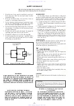
Fig. A.

Using an AC voltmeter to check AC leakage.

1.5 k

0.15 

µ

F

AC
voltmeter
(0.75 V)

To Exposed Metal
Parts on Set

Earth Ground

LEAKAGE TEST

The AC leakage from any exposed metal part to earth ground

and from all exposed metal parts to any exposed metal part having
a return to chassis, must not exceed 0.5 mA (500 microamperes).
Leakage current can be measured by any one of three methods.

1. A commercial leakage tester, such as the Simpson 229 or RCA

WT-540A.  Follow the manufacturers' instructions to use these
instruments.

2. A battery-operated AC milliammeter.  The Data Precision 245

digital multimeter is suitable for this job.

3. Measuring the voltage drop across a resistor by means of a

VOM or battery-operated AC voltmeter.  The “limit” indica-
tion is 0.75V, so analog meters must have an accurate low-
voltage scale.  The Simpson 250 and Sanwa SH-63Trd are ex-
amples of a passive VOM that is suitable.  Nearly all battery
operated digital multimeters that have a 2V AC range are suit-
able.  (See Fig. A)

1. Check the area of your repair for unsoldered or poorly-sol-

dered connections.  Check the entire board surface for solder
splashes and bridges.

2. Check the interboard wiring to ensure that no wires are

“pinched” or contact high-wattage resistors.

3. Look for unauthorized replacement parts, particularly transis-

tors, that were installed during a previous repair.  Point them
out to the customer and recommend their replacement.

4. Look for parts which, though functioning, show obvious signs

of deterioration.  Point them out to the customer and recom-
mend their replacement.

5. Check the line cord for cracks and abrasion. Recommend the

replacement of any such line cord to the customer.

6. Check the B+ voltage to see it is at the values specified.

7. Check the antenna terminals, metal trim, “metallized” knobs,

screws, and all other exposed metal parts for AC leakage.
Check leakage as described below.

SAFETY CHECK-OUT

After correcting the original service problem, perform the following
safety checks before releasing the set to the customer:

Unleaded solder

Boards requiring use of unleaded solder are printed with the lead-
free mark (LF) indicating the solder contains no lead.
(Caution: Some printed circuit boards may not come printed with
the lead free mark due to their particular size.)

 : LEAD FREE MARK

Unleaded solder has the following characteristics.
• Unleaded solder melts at a temperature about 40

°

C higher than

ordinary solder.
Ordinary soldering irons can be used but the iron tip has to be
applied to the solder joint for a slightly longer time.
Soldering irons using a temperature regulator should be set to
about 350

°

C.

Caution: The printed pattern (copper foil) may peel away if the
heated tip is applied for too long, so be careful!

• Strong viscosity

Unleaded solder is more viscous (sticky, less prone to flow) than
ordinary solder so use caution not to let solder bridges occur
such as on IC pins, etc.

• Usable with ordinary solder

It is best to use only unleaded solder but unleaded solder may
also be added to ordinary solder.

www. xiaoyu163. com

QQ 376315150

9

9

2

8

9

4

2

9

8

TEL 13942296513

9

9

2

8

9

4

2

9

8

0

5

1

5

1

3

6

7

3

Q

Q

TEL  13942296513  QQ  376315150  892498299 

TEL  13942296513  QQ  376315150  892498299 

http://www.xiaoyu163.com

http://www.xiaoyu163.com

Summary of Contents for DVP-NS715P

Page 1: ... DIGITAL OUT OPTICAL Optical output jack 18 dBm wave length 660 nm DIGITAL OUT COAXIAL Phono jack 0 5 Vp p 75 ohms COMPONENT VIDEO OUT Y PB PR Phono jack Y 1 0 Vp p PB PR 0 7 Vp p 75 ohms LINE OUT VIDEO 1 2 Phono jack 1 0 Vp p 75 ohms S VIDEO OUT 1 2 4 pin mini DIN Y 1 0 Vp p C 0 286 Vp p 75 ohms General Power requirements 120 V AC 60 Hz Power consumption 13 W Dimensions approx 430 74 255 mm 17 2 ...

Page 2: ...ave a 2V AC range are suit able See Fig A 1 Check the area of your repair for unsoldered or poorly sol dered connections Check the entire board surface for solder splashes and bridges 2 Check the interboard wiring to ensure that no wires are pinched or contact high wattage resistors 3 Look for unauthorized replacement parts particularly transis tors that were installed during a previous repair Poi...

Page 3: ...03 CLOCK GENERATOR Schematic Diagram 4 21 MB 103 I P CONVERTOR Schematic Diagram 4 23 MB 103 VIDEO ENCODER D A CONVERTER Schematic Diagram 4 25 AV 63 Printed Wiring Board 4 27 AV 63 VIDEO BUFFER Schematic Diagram 4 29 AV 63 AUDIO AMP Schematic Diagram 4 31 IF 92 Printed Wiring Board 4 33 IF 92 IF CON Schematic Diagram 4 35 HS12A1U Printed Wiring Board 4 37 HS12A1U Schematic Diagram 4 39 5 IC PIN F...

Page 4: ...Page 2 3 IF 92 Board Page 2 2 MB 103 board Page 2 1 Mechanism Deck Page 2 2 Tray Cover Ass y Page 2 1 Front Panel Block Ass y Page 2 1 www xiaoyu163 com QQ376315150 9 9 2 8 9 4 2 9 8 TEL 13942296513 9 9 2 8 9 4 2 9 8 0 5 1 5 1 3 6 7 3 Q Q TEL 13942296513 QQ 376315150 892498299 TEL 13942296513 QQ 376315150 892498299 http www xiaoyu163 com http www xiaoyu163 com ...

Page 5: ...0 129 A Stand CK 121 board J 6090 132 A FFC 26P J 6090 117 A FFC 9P J 6090 118 A FFC 5P J 6090 119 A FFC 15P J 6090 121 A FFC 25P J 6090 122 A 1 Remove the case from the set Refer to 2 1 2 Remove the MB 103 board from the set Refer to 2 4 3 Set the MB 103 board as shown in Fig 2 Fig 2 4 Set the CK 120 board as shown in Fig 3 Fig 3 2 Four screws B3 3 Connector CN601 4 Connector CN102 5 Connector CN...

Page 6: ...t cable FFC 9P CN204 3 Flexible flat cable FFC 5P CN201 4 Connector CN112 5 Connector CN112 6 Connector CN112 1 Connector CN301 2 Flexible flat cable FFC 25P CN114 3 Connector CN102 4 Harness 6P CN110 Fig 6 www xiaoyu163 com QQ376315150 9 9 2 8 9 4 2 9 8 TEL 13942296513 9 9 2 8 9 4 2 9 8 0 5 1 5 1 3 6 7 3 Q Q TEL 13942296513 QQ 376315150 892498299 TEL 13942296513 QQ 376315150 892498299 http www xi...
Page 7: ...on For more information see the operating instructions for the recording device Note that discs created in the Packet Write format cannot be played CPRM Content Protection for Recordable Media is a coding technology that protects the copyright of images Note on playback operations of DVDs and VIDEO CDs Some playback operations of DVDs and VIDEO CDs may be intentionally set by software producers Si...

Page 8: ...P3 audio track number for DATA CDs Control Menu display 1 m Control Menu display 2 DVD VIDEO CD only m ADVANCED display DVD only See page 46 m Control Menu display off OFF 1 ENGLISH 2 FRENCH 3 SPANISH OFF 1 8 3 4 1 2 2 7 T 1 3 2 5 5 DVD VIDEO PLAY Select Cancel SUBTITLE ENTER RETURN Currently playing chapter number Playing time Total number of chapters Options Current setting Total number of title...

Page 9: ... sun or a lighting apparatus Doing so may cause a malfunction If you do not use the remote for an extended period of time remove the batteries to avoid possible damage from battery leakage and corrosion 16 Step 3 TV Hookups Connect the supplied audio video cord and the power cord in the order 1 3 shown below Be sure to connect the power cord last When connecting to a wide screen TV Depending on th...

Page 10: ...t not all high definition television sets are fully compatible with this product and may cause artifacts to be displayed in the picture In the case of 480 progressive scan picture problems it is recommended that you switch the connection to the standard definition output If there are questions regarding your Sony TV set s compatibility with this model 480p DVD player please contact our customer se...

Page 11: ...TICAL continued 24 Connecting to an AV amplifier receiver with a digital input jack having a Dolby Digital or DTS decoder and 6 speakers This connection will allow you to use the Dolby Digital or DTS decoder function of your AV amplifier receiver You are unable to enjoy the surround sound effects of this player Note After you have completed the connection be sure to set DOLBY DIGITAL to DOLBY DIGI...

Page 12: ...Turn on the amplifier receiver and select the appropriate channel so that you can hear sound from the player 4 Press A on the player and place a disc on the disc tray 5 Press H The disc tray closes and the player starts playback continuous play Adjust the volume on the TV or the amplifier receiver Depending on the disc a menu may appear on the TV screen For DVD VIDEOs see page 32 For VIDEO CDs see...

Page 13: ...A CDs the player enters standby mode Notes MULTI DISC RESUME in CUSTOM SETUP must be set to ON default for this function to work page 68 The resume playback point for the current disc is cleared when you change the play mode you change the settings on the Setup Display This function may not work with some discs Resume Play does not work during Shuffle Play and Program Play H x 32 Using the DVD s M...

Page 14: ...t of MP3 albums appears page 34 the albums are arranged in the following order A t B t C t D t F t G Albums that do not contain tracks such as album E do not appear in the list z Hints If you add numbers 01 02 03 etc to the front of the track file names the tracks will be played in that order Since a disc with many trees takes longer to start playback it is recommended that you create albums of no...

Page 15: ...1 Press DISPLAY twice during playback when playing a CD press once The Control Menu appears REPEAT CLEAR H DISC DISPLAY ENTER X x CLEAR continued 40 2 Press X x to select A B REPEAT then press ENTER The options for A B REPEAT appear 3 Press X x to select SET t then press ENTER The A B REPEAT setting display appears 4 During playback when you find the starting point point A of the portion to be pla...

Page 16: ...ng time of the current chapter When playing a VIDEO CD with PBC functions Playing time of the current scene When playing a VIDEO CD without PBC functions or CD T Playing time of the current track T Remaining time of the current track D Playing time of the current disc D Remaining time of the current disc When playing a DATA CD MP3 audio Playing time of the current track To check the DVD CD text or...

Page 17: ... see which language the code represents When the same language is displayed two or more times the DVD VIDEO is recorded in multiple audio formats When playing a DVD RW The types of sound tracks recorded on a disc are displayed The default setting is underlined Example 1 MAIN main sound 1 SUB sub sound 1 MAIN SUB main and sub sound When playing a VIDEO CD CD or DATA CD MP3 audio The default setting...

Page 18: ...ontrol Menu page 12 Note Depending on the DVD VIDEO you may not be able to change the angles even if multi angles are recorded on the DVD VIDEO Displaying the Subtitles If subtitles are recorded on the discs you can change the subtitles or turn them on and off whenever you want while playing a DVD 1 Press SUBTITLE during playback The following display appears 2 Press SUBTITLE repeatedly to select ...

Page 19: ...nappropriate discs Parental Control Playback of some DVD VIDEOs can be limited according to a predetermined level such as the age of the users Scenes may be blocked or replaced with different scenes The same password is used for both Parental Control and Custom Parental Control Custom Parental Control You can set the same Custom Parental Control password for up to 40 discs When you set the 41st di...

Page 20: ...nes 2424 Portugal 2436 Russia 2489 Singapore 2501 Spain 2149 Sweden 2499 Switzerland 2086 Thailand 2528 United Kingdom 2184 60 Operation Sound Effects Sound Feedback The player beeps when the following operations are performed The default setting of the Sound Feedback function is set to off Setting Sound Feedback 1 Press 1 on the player or the remote The power indicator lights up in green When the...

Page 21: ...e screen MENU DVD VIDEO only You can select the desired language for the disc s menu AUDIO DVD VIDEO only Switches the language of the sound track When you select ORIGINAL the language given priority in the disc is selected SUBTITLE DVD VIDEO only Switches the language of the subtitle recorded on the DVD VIDEO When you select AUDIO FOLLOW the language for the subtitles changes according to the lan...

Page 22: ...nts see Displaying the audio information of the disc page 48 This function affects the output of the following jacks LINE OUT L R AUDIO 1 2 jacks DIGITAL OUT OPTICAL or COAXIAL jack when DOLBY DIGITAL is set to D PCM page 69 DIGITAL OUT Selects if audio signals are output via the DIGITAL OUT OPTICAL or COAXIAL jack Setting the digital output signal Switches the method of outputting audio signals w...

Page 23: ... on the remote page 32 Multi angles are not recorded on the DVD being played continued 72 The angle can only be changed when the ANGLE indicator lights up on the front panel display page 9 The DVD prohibits changing of the angles The player does not operate properly When static electricity etc causes the player to operate abnormally unplug the player Nothing is displayed on the front panel display...

Page 24: ...ican 1097 Czech 1103 Welsh 1105 Danish 1109 German 1130 Bhutani 1142 Greek 1144 English 1145 Esperanto 1149 Spanish 1150 Estonian 1151 Basque 1157 Persian 1165 Finnish 1166 Fiji 1171 Faroese 1174 French 1181 Frisian 1183 Irish 1186 Scots Gaelic 1194 Galician 1196 Guarani 1203 Gujarati 1209 Hausa 1217 Hindi 1226 Croatian 1229 Hungarian 1233 Armenian 1235 Interlingua 1239 Interlingue 1245 Inupiak 12...

Page 25: ... 2 Claw 4 Claw 3 Two claws 5 Two claws 1 Flexible board CN406 6 Front panel block ass y 1 Two flexible flat cables FMO 001 CN201 FMO 002 CN202 1 Flexible flat cable FMM 035 CN402 2 Connector CN101 4 Connector CN601 3 Connector CN102 5 Four screws B3 6 MB 103 board 2 2 TRAY COVER ASS Y REMOVAL 2 3 FRONT PANEL BLOCK ASS Y REMOVAL 2 4 MB 103 BOARD REMOVAL www xiaoyu163 com QQ376315150 9 9 2 8 9 4 2 9...

Page 26: ...MM 035 CN402 9 Screw B3 0 IF 92 board 4 Connector CN102 8 Connector CN102 3 Connector CN201 6 Connector CN102 5 Tape 7 Tape 1 Two screws B3 9 Two screws B3 2 FP support 2 5 POWER BLOCK REMOVAL 2 7 MECHANISM DECK REMOVAL 2 6 AV 63 BOARD REMOVAL 2 8 IF 92 BOARD REMOVAL www xiaoyu163 com QQ376315150 9 9 2 8 9 4 2 9 8 TEL 13942296513 9 9 2 8 9 4 2 9 8 0 5 1 5 1 3 6 7 3 Q Q TEL 13942296513 QQ 376315150...

Page 27: ...al pick up 1 Insulator screw 2 9 OPTICAL PICK UP REMOVAL www xiaoyu163 com QQ376315150 9 9 2 8 9 4 2 9 8 TEL 13942296513 9 9 2 8 9 4 2 9 8 0 5 1 5 1 3 6 7 3 Q Q TEL 13942296513 QQ 376315150 892498299 TEL 13942296513 QQ 376315150 892498299 http www xiaoyu163 com http www xiaoyu163 com ...

Page 28: ...ading not supplied DC motor loading not supplied www xiaoyu163 com QQ376315150 9 9 2 8 9 4 2 9 8 TEL 13942296513 9 9 2 8 9 4 2 9 8 0 5 1 5 1 3 6 7 3 Q Q TEL 13942296513 QQ 376315150 892498299 TEL 13942296513 QQ 376315150 892498299 http www xiaoyu163 com http www xiaoyu163 com ...
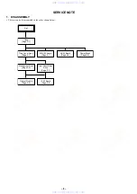
Page 29: ... Block HS12S1U SWITCHING REGULATOR AV 63 AUDIO VIDEO OUT MS 81 LOADING www xiaoyu163 com QQ376315150 9 9 2 8 9 4 2 9 8 TEL 13942296513 9 9 2 8 9 4 2 9 8 0 5 1 5 1 3 6 7 3 Q Q TEL 13942296513 QQ 376315150 892498299 TEL 13942296513 QQ 376315150 892498299 http www xiaoyu163 com http www xiaoyu163 com ...

Page 30: ...CH56 BCK LRCK 16M DRAM 16M SDRAM V Y C Y Cb Cr VIDEO BUFFER SPDIF IC204 IC201 AUDIO AMP IC406 REMOTE COMMANDER RECEIVER EVER 3 3V 11V 5V SW 3 3V 1 8V SW 3 3V 5V SW 11V 11V AUDIO SW 13V INLIMIT SENSOR CHUCK TRAY DETECT HS12S1U BOARD SEE PAGE 4 39 SWITCHING REG AC IN DVD0 7 Y Cb Cr Y0 9 CBCR0 9 PO0 7 05 PB CB COMPONENT VIDEO OUT Y PR CR LINE OUT VIDEO 1 VIDEO 2 2 1 S VIDEO OUT L R LINE OUT AUDIO 2 L...

Page 31: ...39 20 22 16 17 155 GIO2 INT4 05 CHUCK TRAY DETECT S001 1 2 RF A D E H VC PD 24 10 LEDSEL0 SW DVD LD 26 6 Q202 CD LD DRIVE CDLD CD LD VR SLA SLB SPM INLIM TRK 127 ADC3 FCS PS TSD M 40 42 43 VREF 3 3V LDON GIO6 SDI GIO7 SDO GIO8 SCK GIO13 XSDPIT XSDPCS XRST XDRVMUTE OCSW1 SIGO CKSW1 XLDON FE TE PI SSDFCTI SS MON MDSO MDPO SPMUTE SLDA SLDB LMP LMM TSD LMCTL TDRV FDRV SPFG SLE 159 161 162 167 IC301 zx...

Page 32: ...IDEO AUDIO SEE PAGE 3 9 VIDEO AUDIO SEE PAGE 3 9 27MCLK D1CLKO ACH12O LRCKO BCKO ACH12 27MCLK DVD 0 7 LRCK BCK HDATA0 ı HDATA15 HAD0I ı HAD21I HA 0 21 HD 0 15 D 0 7 A 0 7 HA 0 7 84 ı 87 89 ı 92 DVO0 ı DVO7 DVD 0 7 HD 8 15 XRD XWRH RST DM ACK1I DM RQ1O DM ACK0I DM RQ0O ACLK HAD23I HAD22I CLKI SCLKI 200 199 HWAITO HIREQO HA 0 21 HD 0 15 HA 0 21 HD 0 15 XRST 512FSAVD 33MARP XWRH XRD XFRRST XARPIT XAR...

Page 33: ...Q1 DACK1 VIDEO AUDIO SEE PAGE 3 10 SIGNAL PROCESSOR SEE PAGE 3 5 RF SERVO SEE PAGE 3 4 05 33MARP 512FSAVD X102 27MHz 33 1OUT FSEL 512FS2CH XFRRST 59 CS1X 72 XWRL 84 SRAMWE 29 SO1 SO1 30 SC1 SC1 79 XDACS XDACS INT1 CS4X XWAIT 35 XRST XRST VIDEO AUDIO SEE PAGE 3 9 XRST SCL SDA XRST XRD XWRH 512 2OUT 512 1OUT XTI XTO 3 27MAVD 27 1OUT X1 X0 HD 0 15 HA 0 21 XRD XWRH 3 CN101 5 6 8 4 1 WP SCL SDA OCSW1 S...

Page 34: ...56 ı 60 63 ı 67 33 RESETB 22 SCLK 21 SDA 2 ı 9 12 13 P Y 0 ı P Y 9 Y 0 9 52 ı 48 45 ı 41 32 CLKIN 63 CLKIN 2 MA0 ı MA11 80 83 86 89 94 97 3 2 5 6 12 11 10 9 IC201 AUDIO AMP IC601 AUDIO D A CONVERTER SDTI AOUTL AOUTL AOUTR AOUTR 16 DZFL SYSTEM CONTROL SEE PAGE 3 8 SIGNAL PROCESSOR SEE PAGE 3 6 INTERFACE CONTROL SEE PAGE 3 11 J101 2 2 3 BICK 2 LRCK 4 MCLK 1 CSN 6 PDN 5 CCLK 7 CDTI 8 17 15 21 23 22 2...

Page 35: ...413 S407 S404 S402 S401 S403 S406 S412 CURSOR PROG SEG 1 18 DIG 1 13 X401 8MHz ND401 FLUORESCENT INDICATOR TUBE CN406 CURSOR 1 IC406 REMOTE COMMANDER RECEIVER 2 1 CN402 SC0 SI0 SO0 XIFBUSY XIFCS XFRRST 34 O C 35 PLAY SURROUND S409 S408 36 DISPLAY XIN XOUT 1 VOUT 8 RST CURSOR STICK 3 CN401 POWER 1 CN201 1 IC404 3 3 4 Vp p 8 MHz 3 11 3 12 3 6 INTERFACE CONTROL BLOCK DIAGRAM w w w x i a o y u 1 6 3 c...

Page 36: ...1 SHUNT REG PCONT IC403 1 8V REG POWER 30 PONCHK VKK F2 F1 EVER 3 3V EVER 3 3V EVER 3 3V AI 5V 3 3V 5V 1 8V SW 11V 11V 3 3V MNT ND401 FLUORESCENT INDICATOR TUBE Q401 402 T401 DC DC CONVERTER AU 11V PS402 3 VIN 2 VOUT CN401 2 CN403 CN404 PUSH ENTER CN406 EVER 3 3V CURSOR STICK 2 PROG D413 13 3 11 12 8 4 1 5 7 5 CN402 7 3 6 2 1 6 7 SW 11V 11V AUDIO 5V SW 3 3V EVER 3 3V EVER 13V P CONT POWER 3 3V REG...

Page 37: ... CONTROL FILTER FL103 FILTER FL102 FILTER FL201 3 3V FILTER FL105 2 5V FILTER FL104 1 1 8V FILTER FL109 5 CN202 6 5 7 3 11V 3 3V MNT IC405 16M SDRAM IC303 16M DRAM IC503 16M SDRAM IC201 DVD CD RF AMP DIGITAL SERVO IC403 AV DECODER IC301 ARP SERVO DSP VCC MOD LED FILTER FL404 FILTER FL403 FILTER FL402 IC501 2 5V REG 4 VOUT 5 VIN IC502 I P CONVERETER IC505 2 5V REG 4 VOUT 5 VIN IC504 VIDEO ENCODER A...

Page 38: ...internal component C adjustment for repair U B Line V B Line Circled numbers refer to waveforms Voltages are dc between measurement point Readings are taken with a color bar signal on DVD refer ence disc and when playing CD reference disc Readings are taken with a digital multimeter DC 10MΩ Voltage variations may be noted due to normal production tolerances Caution Pattern face side Parts on the p...

Page 39: ..._MNT XIFCS XIFBUSY SO0 SI0 SC0 5V 3 3V M_GND 1 8V XFRRST GND 11V GND LDM OCSW1 LDM CKSW1 GND N C GND EVER 3 3 N C CURSOR VR GND FCS VC TRK SW N C RF A N C H G FCS F CD LD N C VCC E N C B PD D C TRK DVD LD GND MOD LD GND SPM SLA INLIM SLA SPM SLB GND LED SLB MAMUTE ART ALT GND DISCEXT RGBSEL ART RMUTE SPDIF Y G C GND P_GND_2CH WIDE ALT GND GND EUROVY AU 5V LMUTE Cr B P_GND_SPDIF Cb R Y V XIFBUSY IF...

Page 40: ...U SWITCHING REGULATOR AV 63 AUDIO VIDEO OUT MS 81 LOADING M001 5P CN001 1 2 3 4 5 S001 1 2 3 4 5 JL001 JL002 JL003 JL004 JL005 1 A LDM LDM OCSW1 CKSW1 GND MB 100 BOARD 5 10 CN402 SEE PAGE 4 17 LOADING MOTOR DETECT CHUCK TRAY 2 4 5 05 B MS 81 BOARD 3 C Uses unleaded solder w w w x i a o y u 1 6 3 c o m Q Q 3 7 6 3 1 5 1 5 0 9 9 2 8 9 4 2 9 8 T E L 1 3 9 4 2 2 9 6 5 1 3 9 9 2 8 9 4 2 9 8 0 5 1 5 1 3...

Page 41: ...1 A 3 IC104 C 4 IC301 C 3 IC302 C 2 IC403 B 4 IC501 B 1 IC502 B 2 IC601 A 3 MB 103 SIGNAL PROCESS SERVO IF 92 INTERFACE CONTROL Power Block HS12S1U SWITCHING REGULATOR AV 63 AUDIO VIDEO OUT MS 81 LOADING Uses unleaded solder w w w x i a o y u 1 6 3 c o m Q Q 3 7 6 3 1 5 1 5 0 9 9 2 8 9 4 2 9 8 T E L 1 3 9 4 2 2 9 6 5 1 3 9 9 2 8 9 4 2 9 8 0 5 1 5 1 3 6 7 3 Q Q TEL 13942296513 QQ 376315150 89249829...

Page 42: ...IC401 C 3 IC404 B 4 IC405 B 4 IC503 A 2 IC504 B 3 IC505 A 2 Q201 A 1 Q202 A 1 w w w x i a o y u 1 6 3 c o m Q Q 3 7 6 3 1 5 1 5 0 9 9 2 8 9 4 2 9 8 T E L 1 3 9 4 2 2 9 6 5 1 3 9 9 2 8 9 4 2 9 8 0 5 1 5 1 3 6 7 3 Q Q TEL 13942296513 QQ 376315150 892498299 TEL 13942296513 QQ 376315150 892498299 http www xiaoyu163 com http www xiaoyu163 com ...

Page 43: ... 33 R234 33 R236 0 R273 CN203 26P 1 2 3 4 5 6 7 8 9 10 11 12 13 14 15 16 17 18 19 20 21 22 23 24 25 26 2SB1132 T100 QR Q202 2SB1132 T100 QR Q201 CN204 9P 1 2 3 4 5 6 7 8 9 1k R244 FL201 SP3728ACB IC201 1 2 3 4 5 6 7 8 9 10 11 12 13 14 15 16 17 18 19 20 21 22 23 24 25 26 27 28 29 30 31 32 33 34 35 36 37 38 39 40 41 42 43 44 45 46 47 48 49 50 51 52 53 54 55 56 57 58 59 60 61 62 63 64 JL201 JL202 JL2...

Page 44: ... 129 130 131 132 133 134 135 136 137 138 139 140 141 142 143 144 145 146 147 148 149 150 151 152 153 154 155 156 157 158 159 160 161 162 163 164 165 166 167 168 169 170 171 172 173 174 175 176 4700p C316 0 01u C334 CL301 CL302 CL308 CL309 CL313 CL314 CL315 IC303 GM71V18160CT 6TR 1 2 3 4 5 6 7 8 9 10 16 17 18 19 20 21 22 23 26 27 28 29 30 31 32 33 34 35 41 42 43 44 45 46 11 15 36 40 24 25 47 48 49 ...

Page 45: ...ADAD11 ADDT2 ADAD2 ADAD1 ADDT11 ADDT3 ADAD0 ADDT1 ADAD3 ADAD5 ADDT8 ADAD5 ADDT12 ADAD0 ADDT10 ADAD9 ADAD7 ADDT12 ADAD2 ADAD4 ADAD3 ADAD4 ADAD10 ADDT5 ADAD1 ADDT7 ADDT6 ADDT9 ADAD8 ADDT4 ADDT5 ADDT13 ADAD11 ADDT15 ADDT15 ADDT3 ADDT7 SDI0 ADAD7 ADAD10 SDI1 ADDT0 SDI2 ADAD8 ADDT1 SDI3 ADAD9 ADDT14 HD0 HD15 HD14 HD13 HD12 HD11 HD10 HD1 HD9 HD8 HD7 HD6 HD5 HD4 HD3 HD2 HA1 HA2 HA3 HA4 HA5 HA6 HA7 HA8 HA...

Page 46: ...CL202 CL203 CL204 CL205 FAN8034L IC202 1 2 3 4 5 6 14 15 16 17 18 19 20 21 22 23 24 27 28 29 30 31 32 33 34 35 36 40 41 42 43 44 45 46 47 48 50 51 52 49 13 25 26 37 38 39 11 12 9 10 7 8 5P CN201 1 2 3 4 5 1 A FCS FCS TRK TRK SLB SLB SLA SLA SPM SPM CKSW1 SPM LDM LDM OCSW1 SPM SLA SLB CKSW1 LDM OCSW1 LDM SLB SLA FCS FCS TRK TRK FCS FCS TRK TRK SLA SLA SLB SLB SPM SPM OCSW1 GND LDM LDM CKSW1 IN3 IN4...

Page 47: ... IC101 1 2 3 4 5 6 7 8 FL103 FL102 FL106 FL108 RB102 10k 1 2 3 4 5 7 8 9 10 6 1 2 3 4 5 1 A HA12 HA14 HA10 HD8 SI2 HA17 HA5 HA10 HA19 HA1 HD1 HA16 HA11 HA4 HA8 HD4 HD12 HD9 HA9 HA10 HA20 HD10 HA5 HD2 HD3 HD11 HA8 HD15 HD5 HD13 HA12 HA15 SO2 HA21 HD8 HA18 HA6 HD13 HA17 HD10 HD15 HA21 HA1 HD7 HA4 HA5 HA6 HA7 HD7 HD15 HA0 HA6 HA1 HD5 HD14 HD9 HA2 HD12 HA9 HA18 HD10 HA20 HA4 HA13 HD11 HD13 HA9 HD0 HA2...

Page 48: ...4 JL119 JL103 JL106 JL102 JL120 JL111 JL112 JL110 JL113 JL114 JL115 JL130 JL131 JL132 JL133 JL134 JL135 FL110 FL105 FL104 FL101 X102 27MHz FL109 SM8707AV E2 IC103 1 2 3 4 5 6 7 8 9 10 11 12 13 14 15 16 6P CN102 1 2 3 4 5 6 4 7uH L101 1 2 3 4 5 1 A SI0 SO0 SC0 3 3V_MNT GND SO0 XIFBUSY SI0 XIFCS GND XFRRST SC0 27 1OUT VSS VSS VSS 33 1OUT N C VDD VDD XTO 33 2OUT VDD 27 2OUT 512 2OUT FSEL XTI 512 1OUT...

Page 49: ...4 55 56 57 58 59 60 61 62 63 64 65 66 67 68 69 70 71 72 73 74 75 76 77 78 79 80 81 82 83 84 85 86 87 88 89 90 91 92 93 94 95 96 97 98 99 100 101 102 103 104 105 106 107 108 109 110 111 112 113 114 115 116 117 118 119 120 121 122 123 124 125 126 127 128 129 130 131 132 133 134 135 136 137 138 139 140 141 142 143 144 1 2 3 4 1 A 5 Y9 Y7 Y6 Y5 Y4 Y3 Y2 A1 DQ10 A2 DQ11 A3 DQ12 A9 DQ7 DQ6 DQ5 DQ4 DQ3 D...

Page 50: ...04 1 2 3 4 5 6 7 8 9 10 11 12 13 14 15 16 17 18 19 20 21 22 23 24 25 26 27 28 29 30 31 32 33 34 35 36 37 38 39 40 41 42 43 44 45 46 47 48 49 50 51 52 53 54 55 56 57 58 59 60 61 62 63 64 MM1385NNLE IC505 1 2 3 4 5 1 2 3 4 1 A 5 PO0 PO1 Y0 CBCR4 CBCR7 PO2 Y6 CBCR0 CBCR1 CBCR5 Y4 Y7 Y8 Y2 Y5 PO5 Y9 PO6 CBCR9 SDA PO4 SCL CBCR2 Y3 CBCR8 PO3 SDA Y1 SCL CBCR3 CBCR6 PO7 MCLK BICK SDTI LRCK PDN CSN CCLK CD...

Page 51: ...s diagram AV 63 BOARD CN103 A 8 CN202 B 7 D001 A 8 D002 A 8 D003 A 8 D101 A 5 D102 A 5 D103 A 6 D104 A 5 D201 B 1 D202 C 1 D205 C 7 IC101 A 7 IC102 B 5 IC201 B 3 IC203 C 2 IC204 A 2 Q101 B 6 Q105 B 6 Q106 B 4 Q107 B 4 Q201 B 7 Q202 B 1 Q203 C 7 Q204 B 1 Q205 B 1 Q207 A 3 Q208 A 3 Q211 A 2 Q216 B 7 w w w x i a o y u 1 6 3 c o m Q Q 3 7 6 3 1 5 1 5 0 9 9 2 8 9 4 2 9 8 T E L 1 3 9 4 2 2 9 6 5 1 3 9 9...

Page 52: ...TLM E 1 2 3 4 5 6 7 8 9 10 11 12 13 14 15 16 17 18 19 22 23 24 25 26 27 28 29 30 31 32 33 34 35 36 21 20 0 047u C109 220p C103 0 1u C112 0 01u C101 0 1u C114 IC101 NJM79M05DL1A TE2 GND 1 IN 2 OUT 3 Y C G G C G G Y J103 100uH L101 ET101 J101 1 A VIDEO_IN DCCNT1 GND C_IN MUTE1 Y_IN NC DCCNT2 NC GND Y_IN NC DCCNT2 GND Cb_IN MUTE2 Cr_IN 5V VIDEO_OUT GND C_OUT NC Y_OUT 5V NC 5V NC Y_OUT GND Cb_OUT Cr_O...

Page 53: ... 16V 220u C231 16V 47u C229 16V C233 47u 16V 47u C234 560p C202 0 01u C223 C232 220p 180p C203 180p C205 180p C206 0 01u C222 180p C204 560p C201 0 01u C208 0 01u C207 UN2213 TX Q202 7P CN202 1 2 3 4 5 6 7 CN203 25P DTC124TKA T146 Q204 J201 ET202 2SC2712 YG TE85L Q203 TRANSISTOR2SD1938 F ST TX SO Q208 TRANSISTOR2SD1938 F ST TX SO Q207 2SC2712 YG TE85L Q211 1SS355TE 17 D205 BA4558F E2 IC201 1 2 3 4...

Page 54: ... 11 D412 E 11 D413 E 13 IC403 A 10 IC404 D 9 IC405 B 10 IC406 E 12 Q401 D 11 Q402 D 12 Q404 B 13 Q405 B 12 MB 103 SIGNAL PROCESS SERVO IF 92 INTERFACE CONTROL Power Block HS12S1U SWITCHING REGULATOR AV 63 AUDIO VIDEO OUT MS 81 LOADING Uses unleaded solder w w w x i a o y u 1 6 3 c o m Q Q 3 7 6 3 1 5 1 5 0 9 9 2 8 9 4 2 9 8 T E L 1 3 9 4 2 2 9 6 5 1 3 9 9 2 8 9 4 2 9 8 0 5 1 5 1 3 6 7 3 Q Q TEL 13...

Page 55: ...5 JL466 JL467 JL468 JL469 JL470 JL471 JL472 JL473 JL474 JL475 JL476 JL477 JL478 JL479 JL480 JL481 JL482 JL483 JL484 BZ401 MA8068 L TX D412 S 80830ANUP EDT T2 IC405 1 2 3 LMS8117ADTX 1 8 NOPB IC403 1 GND 2 VOUT 3 VIN PS401 PS402 FB401 10P CN405 1 2 3 4 5 6 7 8 9 10 7P CN402 1 2 3 4 5 6 7 UN2111 TX Q405 GP1UD28SYK IC406 1 2 3 SLR 342DCT32 D413 CN403 6P 1 1 8V 2 5V 3 GND 4 SW 3 3V 5 11V 6 M_GND 5P CN...

Page 56: ...63 AUDIO VIDEO OUT MS 81 LOADING HS12S1U BOARD CN101 A 1 CN201 B 4 D101 B 2 D103 A 2 D110 A 3 D211 A 4 D212 A 4 D213 A 4 D221 A 3 D311 A 4 D312 A 4 D313 B 5 D511 B 4 D611 A 4 D612 A 4 D621 A 5 D622 A 5 IC101 A 3 IC301 A 3 IC411 B 5 IC611 A 5 Q211 B 5 Q311 B 4 Q611 A 5 Q621 A 5 Q712 B 5 Uses unleaded solder w w w x i a o y u 1 6 3 c o m Q Q 3 7 6 3 1 5 1 5 0 9 9 2 8 9 4 2 9 8 T E L 1 3 9 4 2 2 9 6 ...

Page 57: ... IC411 XC6201P352TH IC611 PQ12RF11 D611 D2S4M D311 D1NS4 D211 S3L20U D213 D1NS4 6 D313 1SS270A C223 47uF 35V L511 10uH L211 10uH C313 47uF 35V C611 330uF 35V C111 10uF 50V C103 100pF 250V C311 150uF 35V L221 100uH D212 RD33F L311 39uH C221 100uF 35V R303 2 2k PC101 TLP421F R305 390 R304 1 2k R306 1 5k C301 1uF 50V C302 10uF 50V C112 47uF 35V IC301 AN1431T T101 D110 D1NL20U D103 MTZJ7 5 C117 1uF 50...

Page 58: ... XWRH O High byte write enable signal output 16 bit and 8 bit 72 XWRL O Lower byte write enable signal output Pin No Pin name I O Function 1 5 HA17 HA21 O Address bus A17 A21 6 HA22 Not used 7 WP O I2C EEPROM write protect output 8 XSACS Not used 9 AVCC Power supply 3 3 V 10 AVRH Reference power supply 3 3 V 11 AVSS Ground 12 AN0 I Set of mode 0 13 AN1 I Set of mode 1 14 AN2 I Set of mode 2 15 AN3...

Page 59: ...o mute signal output 84 SRAMWE O External RAM write enable signal output 85 92 HD0 HD7 I O Data bus D0 D7 16 bit only 93 100 HD8 HD15 I O Data bus D8 D15 16 bit D0 D7 8 bit 101 VSS Ground 102 109 HA0 HA7 O Address bus A00 A07 110 VCC Power supply 3 3 V 111 118 HA8 HA15 O Address bus A08 A15 119 VSS Ground 120 HA16 O Address bus A16 www xiaoyu163 com QQ376315150 9 9 2 8 9 4 2 9 8 TEL 13942296513 9 ...

Page 60: ...or key to continue the check from the item next to faulty item 6 1 GENERAL DESCRIPTION The Test Mode allows you to make diagnosis and adjustment eas ily using the remote commander and monitor TV The instructions diagnostic results etc are given on the on screen display OSD 6 2 STARTING TEST MODE Press the TOP MENU CLEAR POWER keys on the remote commander in this order with the power of main unit i...

Page 61: ...el code is dis played 2 6 Mount resistance confirmation check Error 22 region code discord Accordance between region codes one is detected with model resistance and destination resistance and the other is detected with region resistance is check If an error is detected the region code determined with re gion resistance is displayed at write data and the region code determined with model resistance...

Page 62: ...ess 0000A55A Write Data 00000000 Read Data 00080000 Press NEXT Key to Continue Press PREV Key to Repeat _ shows the data 0xA55A was read from address 0x00080000 though it was written to the address 0x00000000 This im plies that these addresses are in the form of shadow Also if the read data is not 0xA55A another error will be present 5 5 ARP RAM Check Data write read and accord check Error 11 ARP ...

Page 63: ...5 2 ARP Register Check 5 3 ARP to RAM Data Bus 5 4 ARP to RAM Address Bus 5 5 ARP RAM Check 6 AV Decoder 6 2 1935 RAM 6 3 1935 SP 7 Video 7 2 Color Bar 8 Audio 8 2 ARP 1935 8 3 Test Tone Error Codes List 00 Error not detected 01 RAM write read data discord 02 Gate array NG 03 EEPROM NG 04 Flash memory clear error 05 Flash memory write error 06 Flash memory read data discord 08 ARP register read da...

Page 64: ...essage You can exit the adjustment by pressing the x button In adjusting each disc the mirror time is measured to check the disk type In the auto adjustment whether the disc type is correct is not checked unlike conventional models and accordingly take care not to insert a different type of disc 1 DVD SL single layer Select 1 insert DVD single layer disc and press ENTER key and the adjustment will...

Page 65: ...EEPROM DVD Dual Layer Disc Adjustment Steps 1 Sled Reset 2 Disc Check Memory DL 3 Set Disc Type DL DVD DL Layer 1 Adjust 4 Spdl Start 5 LD ON 6 Fcs ON 1 with PI Level Mesure 7 Auto Track Offset Adjust L1 8 Tracking ON 9 Clva ON 10 Sled ON 11 Auto Focus Balance Adjust 12 Auto Focus Gain Adjust L1 13 Auto Focus Balance Adjust L1 14 Eq Boost Adjust L1 15 Auto Track Gain Adjust L1 16 Jitter Measure DV...

Page 66: ...OM to check the disc type First set a DVD SL disc and press 1 then set a CD disc and press 2 and finally set a DVD DL disc and press 3 The measured mirror time is displayed re spectively The adjustment must be executed more than once after default data were written From this screen you can go to another mode by pressing or key but you cannot enter this mode from another mode You can enter this mod...

Page 67: ...sition This model does not have Tilt device so reset only the Sled to initial position 1 LD Turn ON OFF the laser 2 SP Turn ON OFF the spindle 3 Focus Search the focus and turn on the focus 4 TRK Turn ON OFF the tracking servo 5 Sled Turn ON OFF the sled servo If PLL is not locked or can not be locked the sled servo does not be turned ON Indication remains as OFF 6 CLVA Turn ON OFF normal servo of...

Page 68: ...fset 2 Auto Focus Balance 3 Auto Focus Offset 4 Auto Focus Gain 5 Auto TRK Gain 6 Auto EQ 7 Auto L F Offset 8 Auto Group Delay SA SI EMG 00 DVD SL 12 cm On this screen each item can be adjusted automatically Select the desired number 1 to 8 from the remote commander and se lected item is adjusted automatically 1 Auto TRK Offset Adjusts tracking offset 2 Auto Focus Balance Adjusts focus balance 3 A...

Page 69: ... x key or the RETURN key to return to the Test Mode Menu 6 7 EMERGENCY HISTORY EMG History Laser Hours CD xxhxxm DVD xxhxxm 1 00 00 00 00 00 00 00 00 00 00 00 00 00 00 00 00 2 00 00 00 00 00 00 00 00 00 00 00 00 00 00 00 00 Select 1 9 Scroll UP DOWN 1 Last EMG Exit RETURN On the Test Mode Menu screen selecting 4 displays the infor mation such as servo emergency history The history information from...

Page 70: ...C Power ON after IF CON IC404 was reset the input to 10pin SELF CHECK is judged and if Low is entered the main unit transits to the Self Check mode In this port input judgment the result of 3 time attempts must be same assuming that the MB 103 andAV 63 boards are not connected Whilepressingthe x key on the main unit with the IF CON in STANDBY mode enter RETURN DISPLAY or SET UP on the remote com m...

Page 71: ...OUR MIN SEC A B DVD CD VCD PROGRESSIVE MULTI MP 3 SHUFFLE REPEAT 1 Digital PGM GROUP TITLE TRACK CHAP INDEX ANGLE NTSC HOUR MIN SEC A B DVD CD GROUP TITLE TRACK CHAP INDEX ANGLE NTSC HOUR MIN SEC VCD PROGRESSIVE MULTI MP 3 SHUFFLE REPEAT 1 Digital PGM A B DVD CD VCD PROGRESSIVE MULTI MP 3 SHUFFLE REPEAT 1 Digital PGM A B DVD CD GROUP TITLE TRACK CHAP INDEX ANGLE NTSC HOUR MIN SEC www xiaoyu163 com...

Page 72: ...h the DISPLAY key on the remote commander NOTHING is dis played when nothing is entered Also VIDEO CD DVD and CD segments turn on when a communication error occurred FLD display at input of H key on the main unit Input IC404 Pin No Signal Voltage V Pin ed CURSOR Pin ef O C Pin eg PLAY Pin eh DISPLAY Pin ej POWER 0 0 2 ENTER OPNE CLOSE PLAY STOP POWER 0 6 0 82 DOWN PREVIOUS DISPLAY TVS 1 16 1 47 LE...

Page 73: ... key Remote commander key code display at input of X key Key code 39h VCD PROGRESSIVE MULTI MP 3 SHUFFLE REPEAT 1 Digital PGM GROUP TITLE TRACK CHAP INDEX ANGLE NTSC HOUR MIN SEC A B DVD CD VCD PROGRESSIVE MULTI MP 3 SHUFFLE REPEAT 1 Digital PGM GROUP TITLE TRACK CHAP INDEX ANGLE NTSC HOUR MIN SEC A B DVD CD VCD PROGRESSIVE MULTI MP 3 SHUFFLE REPEAT 1 Digital PGM GROUP TITLE TRACK CHAP INDEX ANGLE...

Page 74: ...FLD turns on and each time the SHUTTLE is entered the segment of each grid is switched in order When SHUTTLE input is clockwise the seg ment switches in 1 2 3 direction or counterclockwise it switches in 3 2 1 direction This tests whether each segment turns on individually Display at the start of Anode Test Input in CW direction PROGRESSIVE MULTI MP 3 SHUFFLE REPEAT 1 Digital PGM GROUP TITLE TRACK...

Page 75: ...odel does not provide JOG SHUTTLE and therefore use another DVD remote commander having the JOG SHUTTLE 2 3 7 2 Operation and Display LED is switched in order by the input of JOG SHUTTLE Also LED ON OFF is switched by the input of same key as the function that turns on the LED concerned FLD display during LED Test 2 3 8 Beep Sound Test 2 3 8 1 Transition Keys in Self Check Mode Input of a key on m...

Page 76: ...e e e e e e e e e e n n n n n n n n n n p p p p p p p p p p r r r r r r r r r r d d d d col d d d d d d Dp col 1G a h j k b f m s g c e n p r d Dp Dp Dp Dp Dp Dp Dp Dp Dp GROUP TITLE CHAP INDEX ANGLE NTSC HOUR MIN SEC 9G a h j k b f m s g c e n p r d Dp TRACK GROUP TITLE 10G TRACK 9G CHAP 8G INDEX 7G ANGLE 6G NTSC 5G HOUR 4G 3G MIN 2G 1G SEC VCD PROGRESSIVE MULTI MP 3 SHUFFLE REPEAT 1 Digital PGM ...

Page 77: ... IC104 with an oscilloscope If the 8 25 MHz signal appears t Check the machine ac cording to section 1 3 1 If the 33 MHz signal appears t Check the machine accord ing to section 1 3 2 If other frequencies are output R110 and R113 have defective soldering X101 crystal os cillator is defective If the measurement point is fixed to either H or L t Observe XFRRST pin uh of SYSCON IC104 with an oscillos...

Page 78: ...r the IC is defective depending on the moving CS signal CS2X CS3X AVD IC403 CS4X CS5X ARP SERVO IC301 If the trouble is not applicable to any of the above phenomenon SYSCON IC104 or ROM IC106 or IC107 is defective 3 If the message SDSP No Ack appears after the menu is displayed 3 1 ARP SERVO clock signal check Check frequency of CLKIN pin zb 33 MHz t Normal Frequency other than 33 MHz t CLKIN is s...

Page 79: ...s abnormal t The power supply block is defec tive or the IF 92 board is defective or MB103 is defective 3 2 Check XFRRST pin 8 at CN101 on the MB 103 board If it is fixed to L t The signal line has defective solder ing or is short circuited with other signal lines or parts are defective 3 3 Check IFBSY pin 5 XIFCS pin 6 SI0 pin 4 SO0 pin 1 and SC0 pin 3 at CN101 If they are fixed to H or L t The s...

Page 80: ...he NTSC monitor Therefore for diag nostic check use the monitor that supports both NTSC and PAL modes Use the reference disc for PAL for check and use the refer ence disc for NTSC for adjustment This section describes procedures and instructions necessary for adjusting electrical circuits in this set Instruments required 1 Color monitor TV 2 Oscilloscope 1 or 2 phenomena band width over 100 MHz wi...

Page 81: ...e NTSC standard and if not adjusted correctly the brightness will be too large or small Mode Video level adjustment in test mode Signal Color bars Test point LINE OUT VIDEO connector 75 Ω terminated Instrument Oscilloscope Adjusting element RV501 Specification 1 00 Vp p Adjusting method 1 In the test mode initial menu 6 Video Level Adjustment set so that color bars are generated 2 Adjust the RV501...

Page 82: ...terminated Instrument Oscilloscope Specification 648 50 mVp p Checking method 1 In the test mode initial menu 6 Video Level Adjustment set so that color bars are generated 2 Confirm that the B Y level is 700 50 mVp p Figure 7 6 7 Checking Component Video Output R Y Purpose This checks component video output R Y If it is incorrect cor rect colors will not be displayed when connected to for instance...

Page 83: ...501 CS OUT COMP OUT 13 1 CN201 IC403 w w w x i a o y u 1 6 3 c o m Q Q 3 7 6 3 1 5 1 5 0 9 9 2 8 9 4 2 9 8 T E L 1 3 9 4 2 2 9 6 5 1 3 9 9 2 8 9 4 2 9 8 0 5 1 5 1 3 6 7 3 Q Q TEL 13942296513 QQ 376315150 892498299 TEL 13942296513 QQ 376315150 892498299 http www xiaoyu163 com http www xiaoyu163 com ...

Page 84: ...té Ne les remplacer que par une pièce portant le numéro spécifié 8 1 1 FRONT PANEL ASSEMBLY Ref No Part No Description Remark Ref No Part No Description Remark 9 3 059 349 11 LEG CUSHION 10 X 3952 245 1 PANEL ASSY FRONT 11 1 757 693 11 CABLE FLEXIBLE FLAT FMO 001 12 1 757 694 11 CABLE FLEXIBLE FLAT FMO 002 13 1 757 697 11 CABLE FLEXIBLE FLAT FMM 035 14 1 477 211 11 REMOTE COMMANDER RMT D145A 15 3 ...

Page 85: ...ark 54 3 073 182 02 BUSHING CODE 55 3 970 608 51 SUMITITE B3 BV 0 51 1 468 650 11 POWER BLOCK HS12S1U 52 3 970 608 01 SUMITITE B3 BVS 0 53 1 783 531 31 CORD POWER www xiaoyu163 com QQ376315150 9 9 2 8 9 4 2 9 8 TEL 13942296513 9 9 2 8 9 4 2 9 8 0 5 1 5 1 3 6 7 3 Q Q TEL 13942296513 QQ 376315150 892498299 TEL 13942296513 QQ 376315150 892498299 http www xiaoyu163 com http www xiaoyu163 com ...

Page 86: ...cified Les composants identifiés par une marque 0 sont critiques pour la sécurité Ne les remplacer que par une pièce portant le numéro spécifié 101 102 102 102 103 103 104 103 not supplied not supplied not supplied not supplied not supplied not supplied not supplied not supplied not supplied not supplied not supplied not supplied www xiaoyu163 com QQ376315150 9 9 2 8 9 4 2 9 8 TEL 13942296513 9 9 ...

Page 87: ...CHIP 0 01uF 10 25V C208 1 162 970 11 CERAMIC CHIP 0 01uF 10 25V C209 1 126 960 11 ELECT 1uF 20 50V C222 1 162 970 11 CERAMIC CHIP 0 01uF 10 25V C223 1 162 970 11 CERAMIC CHIP 0 01uF 10 25V C224 1 126 947 11 ELECT 47uF 20 16V C227 1 126 947 11 ELECT 47uF 20 16V C228 1 126 947 11 ELECT 47uF 20 16V C229 1 126 947 11 ELECT 47uF 20 16V C231 1 126 934 11 ELECT 220uF 20 16V C232 1 163 259 91 CERAMIC CHIP...

Page 88: ...5 1 10W R229 1 216 089 91 RES CHIP 47K 5 1 10W R230 1 216 089 91 RES CHIP 47K 5 1 10W R234 1 216 065 91 RES CHIP 4 7K 5 1 10W R235 1 216 065 91 RES CHIP 4 7K 5 1 10W R238 1 216 097 11 RES CHIP 100K 5 1 10W R240 1 216 041 00 METAL CHIP 470 5 1 10W R241 1 216 041 00 METAL CHIP 470 5 1 10W R242 1 216 041 00 METAL CHIP 470 5 1 10W R243 1 216 041 00 METAL CHIP 470 5 1 10W R249 1 216 033 00 METAL CHIP 2...

Page 89: ...025 11 RES CHIP 100 5 1 10W R481 1 216 025 11 RES CHIP 100 5 1 10W R482 1 216 025 11 RES CHIP 100 5 1 10W R483 1 216 025 11 RES CHIP 100 5 1 10W R484 1 216 025 11 RES CHIP 100 5 1 10W R485 1 216 025 11 RES CHIP 100 5 1 10W R488 1 216 033 00 METAL CHIP 220 5 1 10W R489 1 216 097 11 RES CHIP 100K 5 1 10W R490 1 216 083 00 METAL CHIP 27K 5 1 10W R496 1 216 017 91 RES CHIP 47 5 1 10W R497 1 216 097 11...

Page 90: ...HIP 0 0047uF 10 50V C308 1 126 206 11 ELECT CHIP 100uF 20 6 3V C309 1 162 970 11 CERAMIC CHIP 0 01uF 10 25V C310 1 162 927 11 CERAMIC CHIP 100PF 5 50V C311 1 162 970 11 CERAMIC CHIP 0 01uF 10 25V C312 1 110 563 11 CERAMIC CHIP 0 068uF 10 16V C313 1 164 677 11 CERAMIC CHIP 0 033uF 10 16V C314 1 162 970 11 CERAMIC CHIP 0 01uF 10 25V C315 1 162 970 11 CERAMIC CHIP 0 01uF 10 25V C316 1 162 968 11 CERA...

Page 91: ...NECTOR PC BOARD 6P CN103 1 770 470 21 PIN CONNECTOR PC BOARD 6P CN203 1 815 507 21 CONNECTOR FFC FPC 26P FERRITE BEAD FB103 1 469 324 21 FERRITE 0uH FB104 1 469 324 21 FERRITE 0uH FB105 1 469 324 21 FERRITE 0uH FB106 1 469 324 21 FERRITE 0uH FB107 1 469 324 21 FERRITE 0uH FB108 1 469 324 21 FERRITE 0uH FB109 1 469 324 21 FERRITE 0uH FB111 1 469 324 21 FERRITE 0uH FILTER FL101 1 234 177 21 FERRITE ...

Page 92: ...HIP 680K 5 1 10W R232 1 216 839 11 METAL CHIP 33K 5 1 10W R233 1 216 853 11 METAL CHIP 470K 5 1 10W R234 1 216 803 11 METAL CHIP 33 5 1 10W R235 1 216 809 11 METAL CHIP 100 5 1 10W R236 1 216 803 11 METAL CHIP 33 5 1 10W R238 1 216 839 11 METAL CHIP 33K 5 1 10W R239 1 216 839 11 METAL CHIP 33K 5 1 10W R240 1 216 839 11 METAL CHIP 33K 5 1 10W R241 1 216 839 11 METAL CHIP 33K 5 1 10W R242 1 216 849 ...

Page 93: ...IP 300 0 5 1 10W R578 1 218 834 11 METAL CHIP 300 0 5 1 10W R579 1 218 834 11 METAL CHIP 300 0 5 1 10W R585 1 216 833 11 METAL CHIP 10K 5 1 10W R601 1 216 809 11 METAL CHIP 100 5 1 10W R613 1 216 864 11 SHORT 0 R614 1 216 864 11 SHORT 0 R619 1 216 864 11 SHORT 0 COMPOSITION CIRCUIT BLOCK RB102 1 233 270 11 NETWORK RES 8 GANG 10K VARIABLE RESISTOR RV501 1 223 583 41 RES ADJ CARBON 3 TYPE 1K VIDEO L...

Page 94: ...0 1 2002 5 Published by Quality Assurance Dept www xiaoyu163 com QQ376315150 9 9 2 8 9 4 2 9 8 TEL 13942296513 9 9 2 8 9 4 2 9 8 0 5 1 5 1 3 6 7 3 Q Q TEL 13942296513 QQ 376315150 892498299 TEL 13942296513 QQ 376315150 892498299 http www xiaoyu163 com http www xiaoyu163 com ...
Reviews: