7-1
7-1. POWER SUPPLY CHECK
1. HS12S1U Board
Mode
E-E
Instrument
Digital voltmeter
EVER +3.3 V Check
Test point
CN201 pin
qa
Specification
3.5
±
0.2 Vdc
SW +3.3 V Check
Test point
CN201 pin
8
Specification
3.3
±
0.2 Vdc
+5 V Check
Test point
CN201 pin
qs
Specification
5.0
±
0.3 Vdc
SW +11 V Check
Test point
CN201 pin
6
,
7
Specification
11.0
±
1.0 Vdc
EVER +11 V Check
Test point
CN201 pin
qd
Specification
11.0
±
1.0 Vdc
EVER –13 V Check
Test point
CN201 pin
3
Specification
–13.0
±
1.0 Vdc
Checking method:
1) Confirm that each voltage satisfies the specification.
! Caution
Never touch the heat sink that is the primary part. It is feared that
you may get an electric shock.
SECTION 7
ELECTRICAL ADJUSTMENT
DVP-NS715P
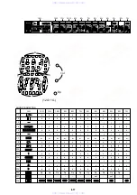
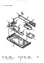
In making adjustment, refer to 7-6. Adjustment
Related Parts Arrangement.
Note:
During diagnostic check, the characters and color bars can
be seen only with the NTSC monitor. Therefore, for diag-
nostic check, use the monitor that supports both NTSC and
PAL modes.
Use the reference disc for PAL for check, and use the refer-
ence disc for NTSC for adjustment.
This section describes procedures and instructions necessary for
adjusting electrical circuits in this set.
Instruments required:
1) Color monitor TV
2) Oscilloscope 1 or 2 phenomena, band width over 100 MHz,
with delay mode
3) Frequency counter (over 8 digits)
4) Digital voltmeter
5) Standard commander (RMT-D145A)
6) DVD reference disc
HLX-501 (J-6090-071-A) (dual layer) (NTSC)
HLX-503 (J-6090-069-A) (single layer) (NTSC)
HLX-504 (J-6090-088-A) (single layer) (NTSC)
HLX-505 (J-6090-089-A) (dual layer) (NTSC)
HLX-506 (J-6090-077-A) (single layer) (PAL)
HLX-507 (J-6090-078-A)(dual layer) (PAL)
7) SACD reference disc
HLXA-509 (J-6090-090-A)
8) Extention Cable (J-6090-107-A)
www. xiaoyu163. com
QQ 376315150
9
9
2
8
9
4
2
9
8
TEL 13942296513
9
9
2
8
9
4
2
9
8
0
5
1
5
1
3
6
7
3
Q
Q
TEL 13942296513 QQ 376315150 892498299
TEL 13942296513 QQ 376315150 892498299


