background image

DVP-PQ1

1-3

1-4 E

Connecting to your TV

You can enjoy standard quality picture and sound using this
connection. Before connecting, make sure that your TV is turned off.
To enjoy better picture and sound, refer to the Brown Side of this
manual. Refer also to the instruction manuals of the components to
be connected.

Connecting
the Player

To AUDIO OUT R

To VIDEO OUT

To AUDIO OUT L

To audio input

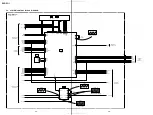
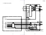
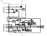
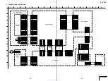
To video input

Basic connection

Basic steps and  tips on playback

You can play DVDs, VIDEO CDs, music CDs, as well as MP3 audio
tracks recorded on a DATA CD*.
Buttons on the player that share the same symbol with buttons on
the remote also share the same function.

*A CD-R/CD-R W/CD-ROM with MP3 audio  tracks  recor ded  on the disc is called  a “DATA CD” in

this manual.

To adjust the TV  volume (for Sony
products only)

Press TV VOL +/–.

Note

This function may not be available depending on the

connected TV.

To play the next or previous
chapter or track

Press 

>

 or 

.

 during playback.

To stop playback

Press 

x

.

The next time you press 

H

, playback  starts

from the same  place.  (Resume  Play)

To play from the beginning

Press 

x

 twice, then press 

H

.

To remove the disc

Hold the  edges  of the  disc  and  pull while
pressing the center .

Playing MP3
audio tracks
from a  list

You can  select  and  play MP3 audio  tracks  from
the list displayed  on the menu.

Selecting an MP3 audio track

1

Press MENU.

Albums containing  MP3 audio tracks  appear.

<TV screen>

2

Select an album using 

V

/

v

, and press

ENTER.

The MP3 audio tracks  contained  in the album
appears.

<TV screen>

3

Select a track using 

V

/

v

, and press

ENTER.

Playback starts.

To display the next or previous page in an
album or track  list

Press 

b

 or 

B

.

To return to the previous screen

Press 

O

.

To turn off the menu

Pr ess MENU once.

Hint

The album or track curr ently being played  is shaded

in the  list.

Notes

On playback

• Only the MP3 audio tracks  displayed  in the list can

be played  on this player (maximum  100 albums  or

200 tracks).

• MP3 audio  tracks  ar e played  in the order displayed

in the  list. This  may  not  coincide  with the  recor ded

order .

• The following audio format files cannot  be played.

– MP3 audio  tracks  not created  accor ding to

ISO9660 Level1/Level2/Joliet.

– MP3 audio  tracks  that do not have  the file name

extension “.MP3.”

– Files with the file name extension “.MP3,” but

are not MP3 audio  tracks.

– Audio tracks  recor ded  in MP3PRO  format.

– MP3 audio  tracks  recor ded  in Packet  Write

format.

– Data  that ar e not MPEG1 Audio Layer 3.

On the display method

• Only the alphabet and numbers can be displayed.

Other characters  appear  as an “*” 

(asterisk).

• This player  cannot  display  ID3 tags.

(stop)

(previous)

>

 (next)

 (remote sensor)

Selected album number

Number of  playable albums in
the disc

album
list

Selected track number

Number of  playable  tracks  in  the
album

track list

White

Red

Yellow

White

Red

Yellow

Notes on  connecting  to your TV

• Do not connect  this player  directly to a

component  such  as  a VCR. If you do, noise
may appear  in the pictur e.

• When connecting  this player to a monaural

TV, use  a ster eo-mono  conversion  cor d (not
supplied).

To insert batteries in the remote

Slide open  the cover . Insert two AA (R6) size
batteries by matching the + and – ends with
the markings  inside the compartment,  and
close the cover .

Connecting the EURO  AV  Adaptor
(For European  models  only)

Attach the Euro AV Adaptor (supplied)  to your
TV. Then,  connect  the  audio/video  cor d to the
corr esponding jacks of 

the Euro 

AV 

Adaptor .

Playing
Discs

See “Using the remote” at the bottom half of this
page for more details on the remote.

For European
models only:
Connect using the
EURO AV Adaptor
(supplied).

TV

Connect the audio/video cord (supplied).

Then, connect the player and the TV to an AC power source (mains).

On your TV :
Turn your TV on and
select the video input.

Turn on the player
by pressing 

?

/

1

(on/standby).

Close the lid until it
clicks.

Place a  disc on the tray.

Place it label-side up (the recorded
side facing down), and press its
center until it clicks into place.


Press 

(play).

To turn off the player

Press 

?

/

1

.

If no buttons  are pressed  for 15 minutes,  the
scr eensaver turns on. 

To 

return to 

the 

normal

scr een, press 

H

.

The player automatically  turns off in another
45 minutes.

If a menu display appears when
you press 

H

In some  DVDs  and  VIDEO CDs,  a  menu  may
appear when you press 

H

. The  menu  usually

enables  you to select  items  such  as  a title
(movie  or album),  audio  language,  or subtitles
by using 

B

/

V

/

v

/

b

 and ENTER. In VIDEO

CDs, this function is called PBC (Playback
Contr ol).
For Asian models  only:
The PBC functions  of Super  VCDs do not work
with this  player .

To return to the menu display while playing
a disc with PBC function

Press 

O

.

To play a disc without using the PBC
function

Press 

>

 or 

.

 during stop to select a track

(picture or music)  that you want to play, and
press 

H

 or ENTER.

To return to PBC Playback

Press 

x

 twice, and press 

H

.

Operating the remote

• Point the remote  at the remote  sensor 

.

When it does  not work, operate  closer to the
remote sensor  .

• Do not expose  the  remote  sensor 

 to direct

sunlight or lighting apparatuses.  Doing so
may cause  a malfunction.

If the aspect ratio of the picture
does not match your TV  type

In “TV TYPE” of the  scr een  setup  setting,
select the setting that matches  your TV. (See
“Settings and Adjustments” for details.)

?

/

1

 indicator

Lights up when
turned on.

AC power
source (mains)

AC power
source (mains)

TV

Video input

Audio input (R)

Audio input (L)

Press 

Z

PUSH, and gently

lift the lid until it clicks.

 H


?

/

1

.

>

x

O

TV VOL (volume) +/–

B

/

V

/

v

/

b

ENTER

Using the
Remote

To change the playing mode, sound
effect, and display, or to use the DVD’s
menu.

c

“Functions”

To read disc information on the screen.

c

“Reading the screen”

Remote

The letters  below correspond  to the letters  in
“Functions.” Use the letters to quickly find the
buttons needed  for each operation.

Settings
and
Adjustments

You can  select  and  change  the settings  of this
player to meet your needs  and to suit your
playing envir onment.

To change the languages used in
subtitles, sound, or on-screen displays.

c

“Language/Screen/Audio Setup”

To adjust the aspect ratio of the picture
to fit your TV.

c

“Language/Screen/Audio Setup”

To select the setting of the audio when
connected to an amplifier.

c

“Language/Screen/Audio Setup”

To set playback limitation levels (such as
to limit violent scenes).

c

“Limiting Playback” (See the
Brown Side of  this manual.)

Press to
turn the
player on.

Press to
adjust the
volume of
Sony TVs.

Press to
cancel the
current
mode.

Current album/title
number
• T: title, A: album

Current chapter/
track/index number

Time display
• D: disc, T: title or track,

C: chapter

• No mark: Playing time

With – : Remaining time

Current audio format (Dolby
Digital, DTS,  PCM,etc.)

Number of  rear
component

Number of  front and
center component

Number of  LFE
(Low Frequency Effect)
component

Functions

Note

Some playback featur

es of DVDs and VIDEO CDs described in the following may be prohibited

by the softwar e producers.  Refer to the instructions  supplied  with the DVDs and VIDEO CDs.

Basic operations  (

A

)

To

Press

play

H

stop

x

pause

X

>

 NEXT or 

.

PREV during playback.

My 

or 

m

y

 during playback.

Press  the button repeatedly  to change  the speed.
To return to normal playback,  press 

H

.

My 

or 

m

y

 during pause.  (DVD/VIDEO CD only.

Functions only in the forwar d direction for VIDEO CDs.)
Press the button r epeatedly to change the playback speed.
To return to normal playback,  press 

H

.

replay

REPLAY

 during playback.  (DVD only)

*See “Understanding  disc str uctur es” in “Playable discs and special words” on the Brown

Side of this manual  for details.

Selecting the playing mode (

B

)

You can  play a selected  title or track randomly  or repeatedly .
To cancel  the operation,  press  the following button repeatedly  to select  “OFF” or
press CLEAR.

To

Press

shuffle

SHUFFLE

 repeatedly during playback. (DVD/VIDEO 

CD/CD

only)

repeat

REPEAT

 repeatedly during playback.

When you select  Repeat  Play during Shuf fle Play, Shuffle Play is
repeated.

Changing the sound (

C

)

You can change the audio language for DVDs r

ecor ded with multilingual tracks.

When listening to a Karaoke  VIDEO CD, you can turn off the vocals. You can also
enjoy this player ’s surr ound effect mode.

To change

Press

language/sound

AUDIO

 repeatedly during playback to select from the options.

In DVDs:

 Select a language  from the options on the scr een.

(When a 4-digit number is displayed, check the number in the
“Language Code List” 

on the Brown Side of this manual.)

In VIDEO CDs/CDs/DATA CDs:

STEREO:

 To hear standar d ster eo sound.

1/L:

 To hear  the sound  of the left channel  from both speakers.

2/R:

 To hear  the sound  of the right channel  from both speakers.

In Super VCDs (For Asian models only):

(The number  befor e the colon shows  the number  of the audio
track being played.  For the meaning  after the colon, see  above.)

1: STEREO

2: STEREO

1: 1/L

2: 1/L

1: 2/R

2: 2/R

SUR

 repeatedly during playback to select from the following.

(DVD only)
To cancel the surr ound setting, press 

SUR

 repeatedly to select

“OFF.”

TVS DYNAMIC:

 To enjoy the surr ound ef fect with your TV’s

speakers. The 

distinct 

sound imaging effect 

is 

as if 

you 

have a

set of additional speakers  next to you.

TVS WIDE:

 To enjoy the surr ound effect with your TV’s

speakers. The 

sound imaging effect 

is 

as if 

you 

have five 

sets

of virtual speakers  filling the  area  surr ounding  you.

TVS NIGHT:

 To enjoy the surr ound mode  at a lower volume.

(Dolby Digital audio  DVD only)

TVS STANDARD:

 To enjoy the surr ound effect with a set of

front speakers connected to the player

. The imaging ef fect is as

if you  have  three  sets  of  additional  speakers  ar ound  you.

Changing the viewing angle and subtitles  (

D

)

You can  select  pictur e angles  if ther e are multiple pictur es  (angles)  recor ded  on the
disc, or change subtitle languages in multilingual DVDs.

To

Press

change angles

ANGLE

 repeatedly during playback to select the number of 

the

angle you want to play. (DVD only)

SUBTITLE

  repeatedly to select the subtitle language. (DVD 

only)

(When a 4-digit number is displayed, check the number in the
“Language Code List” 

on the Brown Side of this manual.)

To cancel the subtitle, press 

SUBTITLE

 repeatedly to select

“OFF.”

Using the DVD’s menu (

E

)

When  a menu  is recor ded  on the DVD, you can  usually  select  items  such  as  the
title, audio  language,  or subtitles.

To display

Press

DVD’s menu

TOP MENU

 or 

MENU

. Select  an  item using 

B

/

V

/

v

/

b

, and

press 

ENTER

. (DVD only)

TOP MENU:

 Displays a menu of available  movie and music

titles.

MENU: 

Displays a menu of subtitles and audio languages.

Displaying information on your screen (

F

)

You can display information such as the playing time or the disc text on the TV
scr een.
To return to the normal scr een, press  DISPLAY repeatedly .

To display

Press

time/text

DISPLAY

 during playback.  Then press 

ENTER

 repeatedly to

switch the display from total playing time to remaining  time,
and vice versa.  (For details, see  “Time display” in the next
section.)
DVD/CD TEXT or MP3 track name will be displayed following
the time display if it is r ecor ded on the disc. (Only the letters of
the alphabet  ar e shown.)

DISPLAY

 twice during playback.  (DVD only)

(For details, see “Audio display” in the next section.)

scan forward  or
backward

play forward or
backward in
slow motion

current audio
format

display or
change subtitles

TV Virtual
Surround settings

Notes

• The surr ound mode

signals are only
output when the
player is connected
via the AUDIO OUT
L/R jack.

• Set the surr ound

settings of the
connected
components (such as
TV) to  off.

• Surr ound does  not

function when a disc
has no rear signal.

B

C

D

E


F

A

go to the next or
previous title* or
track*

Reading the screen

You can  display  the time or audio  format in the
upper ar ea of the TV scr een during playback.

Time display

<Example*>

*Here, the disc is playing chapter  8 of the 11th title, which has

been played for 1 hour 1 minute and 57 seconds.

Audio display

<Example*>

*Here, the indicated  disc’s audio format is Dolby Digital

5.1channel (ch).
5.1ch:

3 (Front Left/Right/Center)  +

2 (Rear  Left/Right) +
0.1 (LFE)

Note

When “DTS” is set to “OFF” in the audio setup

setting, the DTS display will 

not appear  even if the

disc has  a DTS signal. (See  “Settings  and

Adjustments” for details.)

 Selecting the language setup

For the following items,  select  the language  from the Language  List
displayed on the scr een.

Item

Select

OSD

The language you want for the player

’s menu and the

Setup Display.

The language  you want for the menu  recor ded on the
disc.

The language  you want for the sound.
(ORIGINAL: The  language  prioritized  in the  disc  is
automatically chosen.)

The subtitle language.

(AUDIO FOLLOW: The  subtitle  language  changes
accor ding to the audio  language.)

*If 

the language you select her e is 

not recor ded on the disc, another language will

be automatically  selected  from the disc.

Hint

When you select  “OTHERS,” enter  the language  code  from the list on the Brown

Side of this manual  using 

V

/

v

/

b

.

 Selecting the screen setup

Item

Select

16:9

• 4:3 LETTER BOX

• 4:3 PAN SCAN

AUTO:

 For a DUAL  color system TV . (Default

setting)

PAL: 

For a PAL color system  TV.

NTSC:

 For an NTSC color system  TV.

*The setting r ecorded on the disc has priority.

 Selecting the audio setup

Item

Select

OFF:

 Standar d setting.

ON:

 When the playback  sound  is distorted.

(See “Connecting Other Components”  on the Brown
Side of this manual  for instr uctions on this
connection.)

OFF:

 When connecting  a TV or an amplifier to

AUDIO OUT L/R.

ON:

 When connecting  an amplifier with a digital

input jack, etc.,  to DIGITAL OUT (COAXIAL).

(See “Connecting Other Components”  on the Brown
Side for instr uctions on this connection.)

D-PCM:

 Standar d setting.

DOLBY DIGITAL:

 When connecting  to an amplifier

with a  built-in Dolby Digital decoder .

(See “Connecting Other Components”  on the Brown
Side for instr uctions on this connection.)

PCM:

 Standar d setting.

MPEG:

 When connecting  to an amplifier with a

built-in MPEG  audio  decoder .

(See “Connecting Other Components”  on the Brown
Side for instr uctions on this connection.)

OFF:

 Standar d setting.

ON:

 When connecting  to an amplifier with a

built-in DTS decoder .

Hint

The underlined  settings  are the default settings.

AUDIO*

(DVD only)

SUBTITLE*

(DVD only)

TV TYPE*

(Change this to fit
the picture to your
TV.)

For a wide-scr een  TV or a TV
with wide  mode  function.

For a standar d TV. Displays  a
wide pictur e to fit the width of
the scr een  while keeping  the same
aspect ratio.

For a standar d TV. Cuts  off
portions  of a wide pictur e in
order to fit the width of the
screen.

AUDIO ATT

(Audio attenuation)

DIGITAL OUT

(Adjust only when
using a coaxial
digital cord.)

DOLBY DIGITAL

(Adjust only when
“DIGITAL OUT” is set
to “ON.”)

MPEG

(For European/Asian

models only)
(Adjust only when
“DIGITAL OUT” is set
to “ON.”)

DTS

(Adjust only when
“DIGITAL OUT” is set
to “ON.”)

COLOR SYSTEM

(For Asian models only)
(Select when playing a
VIDEO CD.)

MENU*

(DVD only)

Language/Screen/Audio Setup

You can change the languages for the OSD (on-
scr een display) and sound,  and adjust the
video and audio output to match the
components (such as TV) 

your 

player is

connected to.

Setup Display

The numbers  correspond  to the steps  in the procedur e given
below .

1

Press DISPLAY repeatedly in stop mode to
show Setup Display.

2

Select the setup item using 

V

/

v

, and press

ENTER.

LANGUAGE SETUP:

 To change the

language setting.

CUSTOM SETUP: 

To change settings other

than the language.

3

Select an item (e.g., “OSD”) using 

V

/

v

,

and press ENTER.

Refer to the list on the right for details.

4

Select a setting (e.g., “ENGLISH”) using

V

/

v

, and press ENTER.

Refer to the list on the right for details.

To turn off Setup Display:

Press DISPLAY repeatedly  until the display
disappears.

TOP MENU

=/1

TV VOL

CLEAR

REPLAY

STOP

PAUSE

PLAY

PREV

NEXT

ANGLE

SUBTITLE

SHUFFLE

AUDIO

REPEAT

SUR

RETURN

MENU

DISPLAY

ENTER

x

X

H

.

>

m

M

+

SCAN/SLOW

O

        1 (   3 0 )

R O C K   B E S T   H I T
K A R A O K E
J A Z Z
R & B
M Y   F A V O R I T E   S O N G S
C L A S S I C A L
S A L S A   O F   C U B A
B O S S A N O V A

      J A Z Z
            1 (   9 0 )

0 1 S H E   I S   S P E C I A L
0 2 A L L   Y O U   N E E D   I S   . . .
0 3 S P I C Y   L I F E
0 4 H A P P Y   H O U R
0 5 R I V E R   S I D E
0 6                       5
0 7 T A K E   T I M E , T A K E   T I M E

O

TOP MENU

=/1

TV VOL

CLEAR

REPLAY

STOP

PAUSE

PLAY

PREV

NEXT

ANGLE

SUBTITLE

SHUFFLE

AUDIO

REPEAT

SUR

RETURN

MENU

DISPLAY

ENTER

x

X

H

.

>

m

M

+

SCAN/SLOW

T11 —  8  T 1:01:57

DOLBY DIGITAL

3 /2 .1

LANGUAGE SETUP

OSD:
MENU:
AUDIO:
SUBTITLE:

ENGLISH
ENGLISH

ORIGINAL

AUDIO FOLLOW

2

3

4

Ther e is a tactile dot on 

and the “+” button of

TV VOL

.

w w w . x i a o y u 1 6 3 . c o m

Q Q 3 7 6 3 1 5 1 5 0

9

9

2

8

9

4

2

9

8

T E L

1 3 9 4 2 2 9 6 5 1 3

9

9

2

8

9

4

2

9

8

0

5

1

5

1

3

6

7

3

Q

Q

TEL  13942296513  QQ  376315150  892498299 

TEL  13942296513  QQ  376315150  892498299 

http://www.xiaoyu163.com

http://www.xiaoyu163.com

Summary of Contents for DVP-PQ1 Marketing

Page 1: ...02 003 US Model Canadian Model AEP Model UK Model E Model Mexican Model DVP PQ1 RMT D148A www xiaoyu163 com QQ376315150 9 9 2 8 9 4 2 9 8 TEL 13942296513 9 9 2 8 9 4 2 9 8 0 5 1 5 1 3 6 7 3 Q Q TEL 13942296513 QQ 376315150 892498299 TEL 13942296513 QQ 376315150 892498299 http www xiaoyu163 com http www xiaoyu163 com ...

Page 2: ... 62 A 6060 822 A IF 95 BOARD COMPLETE AEP UK 63 A 6060 771 A MB 103PICO UC BOARD COMPLETE US CND 63 A 6060 794 A MB 103PICO E1 BOARD COMPLETE AE1 UK 63 A 6060 802 A MB 103PICO E2 BOARD COMPLETE AE2 63 A 6060 807 A MB 103PICO GA BOARD COMPLETE E 63 A 6061 200 A MB 103PICO MX2 BOARD COMPLETE MX Former Type New Type Ref No Part No Description Remark Ref No Part No Description Remark not supplied not ...

Page 3: ...X A 6060 822 A IF 95 BOARD COMPLETE AEP UK Ref No 1 000 Series A 6060 771 A MB 103PICO UC BOARD COMPLETE US CND A 6060 794 A MB 103PICO E1 BOARD COMPLETE AE1 UK A 6060 802 A MB 103PICO E2 BOARD COMPLETE AE2 A 6060 807 A MB 103PICO GA BOARD COMPLETE E A 6061 200 A MB 103PICO MX2 BOARD COMPLETE MX Ref No 2 000 Series Page Former Type New Type Ref No Part No Description Remark Ref No Part No Descript...

Page 4: ... Published by Quality Assurance Dept DVP PQ1 www xiaoyu163 com QQ376315150 9 9 2 8 9 4 2 9 8 TEL 13942296513 9 9 2 8 9 4 2 9 8 0 5 1 5 1 3 6 7 3 Q Q TEL 13942296513 QQ 376315150 892498299 TEL 13942296513 QQ 376315150 892498299 http www xiaoyu163 com http www xiaoyu163 com ...

Page 5: ...bles 03 020 US Model Canadian Model AEP Model UK Model E Model Mexican Model DVP PQ1 RMT D148A www xiaoyu163 com QQ376315150 9 9 2 8 9 4 2 9 8 TEL 13942296513 9 9 2 8 9 4 2 9 8 0 5 1 5 1 3 6 7 3 Q Q TEL 13942296513 QQ 376315150 892498299 TEL 13942296513 QQ 376315150 892498299 http www xiaoyu163 com http www xiaoyu163 com ...
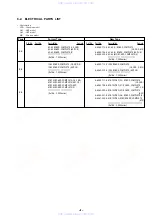
Page 6: ...2003H0500 1 2003 8 Published by Customer Support Dept 64 1 824 114 11 FLEXIBLE FLAT CABLE FIS 003 65 1 824 116 11 FLEXIBLE FLAT CABLE FMP 004 66 1 824 117 11 FLEXIBLE FLAT CABLE FMP 005 Former Type New Type Ref No Part No Description Remark Ref No Part No Description Remark not supplied not supplied not supplied www xiaoyu163 com QQ376315150 9 9 2 8 9 4 2 9 8 TEL 13942296513 9 9 2 8 9 4 2 9 8 0 5 ...

Page 7: ...Asian models 220 240V 50 60Hz Power consumption 9W Dimensions approx 190 135 235mm 7 5 9in w h d Mass approx 1 3kg 2 9lbs Operating temperature 5 C to 35 C 41F to 95F Operating humidity 25 80 Supplied accessories Operating Instructions 1 Audio video cord 1 Remote 1 AA R6 size batteries 2 EURO AV adaptor For European models only 1 Design sheet Specifications and design are subject to change without...

Page 8: ... and Sanwa SH 63Trd are ex amples of a passive VOM that is suitable Nearly all battery operated digital multimeters that have a 2V AC range are suit able See Fig A 1 Check the area of your repair for unsoldered or poorly sol dered connections Check the entire board surface for solder splashes and bridges 2 Check the interboard wiring to ensure that no wires are pinched or contact high wattage resi...

Page 9: ...oard 4 21 AV 65 AUDIO VIDEO OUT Schematic Diagram 4 23 IF 95 Printed Wiring Board 4 25 IF 95 IF CON Schematic Diagram 4 27 SW 370 FUNCTION SWITCH Printed Wiring Board and Schematic Diagram 4 29 SW 371 DOOR SWITCH Printed Wiring Board and Schematic Diagram 4 31 DPSN 20CP SWITCHING REGULATOR Printed Wiring Board US CND 4 32 DPSN 20CP SWITCHING REGULATOR Schematic Diagram US CND 4 33 DPSN 20CP 2 SWIT...

Page 10: ...in the base unit is easily damaged by static electricity desolder the laser tap of the flexible board of the base unit when using it Before disconnecting the connector solder first Before connect ing the connector be careful not to remove the solder Also take adequate measures to prevent damage by static electricity Handle the flexible board with care as it breaks easily Base unit Laser tap www xi...

Page 11: ...olders made to r ecord MP3 audio tracks on a disc 4 Audio data recor ded in MP3 format MP3 files Understanding special words Dolby Digital Digital audio compr ession technology developed by Dolby Laboratories Conforms to 5 1ch surround mode Manufactur ed under license from Dolby Laboratories Dolby Pro Logic and the double D symbol are trademarks of Dolby Laboratories DTS Digital audio compr ession...

Page 12: ...rom the options In DVDs Select a language from the options on the screen When a 4 digit number is displayed check the number in the Language Code List on the Brown Side of this manual In VIDEO CDs CDs DATA CDs STEREO To hear standar d ster eo sound 1 L To hear the sound of the left channel from both speakers 2 R To hear the sound of the right channel from both speakers In SuperVCDs For Asianmodels...

Page 13: ... you tighten four screws in order not to make a crevice between a disk base and a lower case please hold from both sides 3 Two screws BV3 10 5 Two screws BV3 10 8 BU holder 1 Flexible flat cable FIS 003 CN811 2 Connector CN950 7 Two screws BV3 10 6 Four screws BV3 10 4 SW panel assembly 1 Three INS screws 2 Base unit 3 Two flexible flat cables FMP 004 005 www xiaoyu163 com QQ376315150 9 9 2 8 9 4 ...

Page 14: ...tching regulator block 2 Power cord connector 1 Lower case 1 Two screws BV3 10 black 2 3 Jack plate 2 SW 370 board 1 Three screws BV3 10 www xiaoyu163 com QQ376315150 9 9 2 8 9 4 2 9 8 TEL 13942296513 9 9 2 8 9 4 2 9 8 0 5 1 5 1 3 6 7 3 Q Q TEL 13942296513 QQ 376315150 892498299 TEL 13942296513 QQ 376315150 892498299 http www xiaoyu163 com http www xiaoyu163 com ...

Page 15: ...wo connectors CN809 813 3 Connector CN801 3 Three screws B3 1 Flexible flat cable FMV 021 CN100 2 Connector CN301 4 AV 65 board 1 Two screws BV3 6 3 Two screws BV3 6 2 Shield plate jack 4 Shield plate www xiaoyu163 com QQ376315150 9 9 2 8 9 4 2 9 8 TEL 13942296513 9 9 2 8 9 4 2 9 8 0 5 1 5 1 3 6 7 3 Q Q TEL 13942296513 QQ 376315150 892498299 TEL 13942296513 QQ 376315150 892498299 http www xiaoyu16...

Page 16: ...CONTROL MB 103 SIGNAL PROCESS SERVO SWITCHING REGULATOR DPSN 20CP US CND DPSN 20CP 2 AEP UK E www xiaoyu163 com QQ376315150 9 9 2 8 9 4 2 9 8 TEL 13942296513 9 9 2 8 9 4 2 9 8 0 5 1 5 1 3 6 7 3 Q Q TEL 13942296513 QQ 376315150 892498299 TEL 13942296513 QQ 376315150 892498299 http www xiaoyu163 com http www xiaoyu163 com ...

Page 17: ... DRAM 16M SDRAM V Y C VIDEO BUFFER SPDIF IC202 AUDIO AMP IC900 REMOTE COMMANDER RECEIVER EVER 3 3V 11V 5V SW 3 3V 1 8V SW 3 3V 5V SW 11V 11V AUDIO INLIMIT SENSOR SWITCHING REGULATOR DPSN 20CP US CND DPSN 20CP 2 AEP UK E SEE PAGE 4 33 to 4 36 SWITCHING REG AC IN 05 VIDEO OUT S VIDEO OUT L R AUDIO OUT DIGITAL OUT COAXIAL J201 2 3 F1 AI 5V EVER 3 3V AU 11V REG IC104 SYSTEM CONTROL IC107 OTP or IC601 ...

Page 18: ...19 39 20 22 16 17 155 GIO2 INT4 05 1 2 RF A D E H VC PD 24 10 LEDSEL0 SW DVD LD 26 6 Q202 CD LD DRIVE CDLD CD LD VR SLA SLB SPM INLIM TRK 127 ADC3 FCS PS TSD M 40 42 43 VREF 3 3V LDON GIO6 SDI GIO7 SDO GIO8 SCK GIO13 XSDPIT XSDPCS XRST XDRVMUTE RF XLDON FE TE PI SSDFCTI SS MON MDSO MDPO SPMUTE SLDA SLDB LMP LMM TSD LMCTL TDRV FDRV SPFG SLE 159 161 162 167 IC301 zxb DVD play 100 mV DIV 50 ms DIV 16...

Page 19: ...E RAS LCAS UCAS VIDEO AUDIO SEE PAGE 3 9 VIDEO AUDIO SEE PAGE 3 10 ACH12O LRCKO BCKO ACH12 LRCK BCK HDATA0 ı HDATA15 HAD0I ı HAD21I HA 0 21 HD 0 15 D 0 7 A 0 7 HA 0 7 HD 8 15 XRD XWRH RST DM ACK1I DM RQ1O DM ACK0I DM RQ0O ACLK HAD23I HAD22I CLKI SCLKI 200 199 HWAITO HIREQO HA 0 21 HD 0 15 HA 0 21 HD 0 15 XRST 512FSAVD 33MARP XWRH XRD XFRRST XARPIT XARPCS XWAIT XAVDCS2 XAVDCS3 27MAVD XAVDIT DREQ0 D...

Page 20: ... DREQ1 DACK1 VIDEO AUDIO SEE PAGE 3 10 SIGNAL PROCESSOR SEE PAGE 3 5 RF SERVO SEE PAGE 3 4 05 33MARP 512FSAVD X102 27MHz 33 1OUT FSEL 512FS2CH XFRRST 59 CS1X 72 XWRL 84 SRAMWE 29 SO1 SO1 30 SC1 SC1 79 XDACS XDACS INT1 CS4X XWAIT 35 XRST XRST XRST XRD XWRH 512 2OUT 512 1OUT XTI XTO 3 27MAVD 27 1OUT X1 X0 HD 0 15 HA 0 21 XRD XWRH 3 CN101 5 6 8 4 1 WP SCL SDA SCL SDA WP WIDE XARPRST AUDIO VIDEO SEE P...

Page 21: ...01 3 3 3 BICK 2 LRCK 4 MCLK 1 CSN 6 PDN 5 CCLK 7 CDTI 8 17 15 21 23 22 24 20 DIGITAL OUT COAXIAL CN301 5 SPDIF LRCK SC1 SO1 XRST 512FS2CH XDACS MAMUTE D201 Q200 BUFFER Q208 MUTE Q207 MUTE 7 1 Q201 202 203 MUTE DRIVE AUDIO OUT R L A MUTE 6 VMUTE 9 11 5 3 4 2 6 10 V Y C ALT ALT ART ART LMUTE RMUTE MAMUTE SPDIF 16 14 9 12 D202 Q204 205 206 MUTE DRIVE AEP UK E SIGNAL PROCESSOR SEE PAGE 3 6 DZFR R246 R...

Page 22: ...VOUT 3 RESET 12 13 9 11 10 8 7 6 1 1 VOUT IC900 REMOTE COMMANDER RECEIVER S900 H D901 I 1 Q900 LED DRIVE S901 x S902 S903 I 1 S904 1 2 S951 S950 1 2 S950 951 COVER OPEN CLOSE DETECT SW 370 BOARD SEE PAGE 4 29 SW 371 BOARD SEE PAGE 4 31 12 13 9 11 10 8 7 6 1 10 R43 AIN3 P CONT 15 R53 AIN7 IC804 IF CON 12 8 CN811 CN900 CN950 POWER 1 SEE PAGE 3 14 CN901 IC804 1 3 4 Vp p 8 MHz w w w x i a o y u 1 6 3 ...

Page 23: ... 11V 3 3V MNT AU 11V PS801 1 VIN 3 VOUT CN801 2 CN809 CN807 CN901 EVER 3 3V 3 3 11 9 10 6 4 1 5 7 2 CN810 4 1 1 4 5 SW 11V 11V AUDIO 5V SW 3 3V EVER 3 3V P CONT 3 3V REG IC900 REMOTE COMMANDER RECEIVER D901 I 1 SW 370 BOARD SEE PAGE 4 29 F401 US CND Q1 INTERFACE CONTROL SEE PAGE 3 11 SWITCHING REGULATOR DPSN 20CP US CND DPSN 20CP 2 AEP UK E SEE PAGE 4 33 to 4 36 Abbreviation CND Canadian AEP UK E ...

Page 24: ...Q292 FILTER FL110 7 4 IC104 SYSTEM CONTROL FILTER FL103 FILTER FL102 FILTER FL201 3 3V FILTER FL105 2 5V FILTER FL104 1 1 8V FILTER FL109 5 CN301 L103 1 2 4 11V 3 3V MNT IC405 16M SDRAM IC303 16M DRAM IC201 DVD CD RF AMP DIGITAL SERVO IC403 AV DECODER IC301 ARP SERVO DSP VCC MOD LED FILTER FL404 FILTER FL403 FILTER FL402 IC402 3 3V REG 4 VOUT 5 VIN AU 5V IC103 PLL FILTER FL101 IC107 16M FLASH IC10...

Page 25: ...sistor C panel designation f internal component C adjustment for repair U B Line V B Line Circled numbers refer to waveforms Voltages are dc between measurement point Readings are taken with a color bar signal on DVD reference disc and when playing CD reference disc Readings are taken with a digital multimeter DC 10MΩ Voltage variations may be noted due to normal production toler ances Caution Pat...

Page 26: ...SW N C B CD LD N C SPM FCS TRK D VR N C SPM SLB H N C GND SLA E TRK LD GND GND GND G SLB MOD F FCS INLIM C A RF VCC VC SLA LED DVD LD PD B PD VCC MOD SLB GND VR D SLA TRK C RF SLB GND SPM GND TRK E FCS INLIM A G N C LD GND SLA SPM FCS DVD LD H CD LD N C VC F N C SW N C LED OPTICAL DEVICE BASE UNIT KHM 275AHA SERVICE ASSY FFC FMP 004 FFC FMP 005 M SPILDLE MOTOR SLED M MOTOR P CONT M_GND SW 11V M_GN...

Page 27: ...104 C 4 IC301 C 3 IC302 C 2 IC403 B 4 IC501 B 1 IC502 B 2 IC601 A 3 US CND E AEP UK SW 370 FUNCTION SWITCH SW 371 DOOR SWITCH AV 65 AUDIO VIDEO OUT IF 95 INTERFACE CONTROL MB 103 SIGNAL PROCESS SERVO SWITCHING REGULATOR DPSN 20CP US CND DPSN 20CP 2 AEP UK E Uses unleaded solder w w w x i a o y u 1 6 3 c o m Q Q 3 7 6 3 1 5 1 5 0 9 9 2 8 9 4 2 9 8 T E L 1 3 9 4 2 2 9 6 5 1 3 9 9 2 8 9 4 2 9 8 0 5 1...

Page 28: ...4 IC405 B 4 IC503 A 2 IC504 B 3 IC505 A 2 Q201 A 1 Q202 A 1 4 7 4 8 US CND E AEP UK w w w x i a o y u 1 6 3 c o m Q Q 3 7 6 3 1 5 1 5 0 9 9 2 8 9 4 2 9 8 T E L 1 3 9 4 2 2 9 6 5 1 3 9 9 2 8 9 4 2 9 8 0 5 1 5 1 3 6 7 3 Q Q TEL 13942296513 QQ 376315150 892498299 TEL 13942296513 QQ 376315150 892498299 http www xiaoyu163 com http www xiaoyu163 com ...

Page 29: ... R236 0 R273 CN203 26P 1 2 3 4 5 6 7 8 9 10 11 12 13 14 15 16 17 18 19 20 21 22 23 24 25 26 2SB1132 T100 QR Q202 2SB1132 T100 QR Q201 CN204 9P 1 2 3 4 5 6 7 8 9 1k R244 FL201 SP3728ACB IC201 1 2 3 4 5 6 7 8 9 10 11 12 13 14 15 16 17 18 19 20 21 22 23 24 25 26 27 28 29 30 31 32 33 34 35 36 37 38 39 40 41 42 43 44 45 46 47 48 49 50 51 52 53 54 55 56 57 58 59 60 61 62 63 64 JL201 JL202 JL203 JL205 JL...

Page 30: ... C334 CL301 CL302 CL308 CL309 CL313 CL314 CL315 IC303 GM71V18160CT 6TR 1 2 3 4 5 6 7 8 9 10 16 17 18 19 20 21 22 23 26 27 28 29 30 31 32 33 34 35 41 42 43 44 45 46 11 15 36 40 24 25 47 48 49 50 IC302 MM1385ENLE 1 2 3 4 5 1 A JL411 TCK TMS XFRRST RAMD15 RAMD13 RAMD14 RAMD10 RAMD9 SDI2 RAMD11 RAMD12 RAMD8 SDI7 SDI0 SDI6 SDI5 SDI3 SDI4 SDI1 RAMD6 RAMD5 RAMD4 RAMD3 RAMD2 RAMD1 RAMD7 RAMD0 RAMA9 RAMA8 ...

Page 31: ... SDI4 SDI5 SDI6 SDI7 ADAD6 ADDT2 ADDT6 ADAD6 ADDT14 ADAD11 ADDT2 ADAD2 ADAD1 ADDT11 ADDT3 ADAD0 ADDT1 ADAD3 ADAD5 ADDT8 ADAD5 ADDT12 ADAD0 ADDT10 ADAD9 ADAD7 ADDT12 ADAD2 ADAD4 ADAD3 ADAD4 ADAD10 ADDT5 ADAD1 ADDT7 ADDT6 ADDT9 ADAD8 ADDT4 ADDT5 ADDT13 ADAD11 ADDT15 ADDT15 ADDT3 ADDT7 SDI0 ADAD7 ADAD10 SDI1 ADDT0 SDI2 ADAD8 ADDT1 SDI3 ADAD9 ADDT14 HD0 HD15 HD14 HD13 HD12 HD11 HD10 HD1 HD9 HD8 HD7 HD...

Page 32: ...8 JL247 16V 47u C271 CL201 CL202 CL203 CL204 CL205 FAN8034L IC202 1 2 3 4 5 6 14 15 16 17 18 19 20 21 22 23 24 27 28 29 30 31 32 33 34 35 36 40 41 42 43 44 45 46 47 48 50 51 52 49 13 25 26 37 38 39 11 12 9 10 7 8 1 A FCS FCS TRK TRK SLB SLB SLA SLA SPM SPM CKSW1 SPM OCSW1 SPM SLA SLB CKSW1 OCSW1 SLB SLA FCS FCS TRK TRK FCS FCS TRK TRK SLA SLA SLB SLB SPM SPM IN3 IN4 OUT1 IN4 IN1 IN3 OUT3 OUT2 IN5 ...

Page 33: ... 2 3 4 5 1 A R169 R164 HA12 HA10 HD8 SI2 HA17 HA5 HA19 HD1 HA16 HA4 HA8 HD12 HD9 HA9 HA10 HA20 HD10 HA5 HD2 HD11 HA8 HA15 SO2 HA18 HA6 HD13 HA17 HD15 HA21 HA1 HD7 HA4 HA6 HD15 HA0 HA1 HD5 HD9 HA9 HA18 HD10 HA20 HA13 HD11 HD13 HD0 HA2 HD14 HA7 HD7 HD3 HD4 HD6 HA7 HA14 HA3 HD8 HD4 HD0 HA14 HA12 HA16 HD12 HA15 HA11 HA3 HA13 HD6 HD3 HD1 HA11 HD5 HD2 HD14 HA2 HA19 HA16 HA21 HD4 HA20 HA4 HD2 HA17 HA15 H...

Page 34: ...L112 2 16V C127 47u X102 27MHz FB104 6P CN102 1 2 3 4 5 6 JL103 FL109 0 01u C105 22 R137 3 FL105 JL130 100 R183 JL133 JL101 FL101 5V 2 2 R108 4 JL113 100u C126 6 3V 4V 100u C103 0 R181 1 8V FB108 1 0 01u C110 JL131 JL134 JL114 9p C106 4V 47u C125 M_GND JL104 FB105 JL105 FB111 100 R180 0 R157 FB603 FB602 C124 0 1u SI0 SO0 SC0 MCLK BICK SDTI LRCK PDN CSN CCLK CDTI DZFL DZFR VDD VSS AOUTL AOUTL AOUTR...

Page 35: ...C B E Q201 C B E Q202 C B E Q203 Q204 C B E C B E Q205 C B E Q206 R221 R222 C B E Q292 JL124 JL127 JL128 R223 R227 JL225 JL226 JL300 JL301 JL302 JL303 JL304 JL305 JL306 JL307 JL308 JL309 JL310 JL311 JL312 JL313 JL314 JL315 JL405 JL406 JL407 JL409 JL410 16 1 8 9 IC101 D103 C A K D104 C A K C130 R228 R230 C128 C B E Q294 R154 C144 R231 R238 R239 R240 R241 JR104 R245 R246 R247 R248 R249 FB250 FB251 J...

Page 36: ...UTE 2 INA 3 GND 4 INB 5 GND 6 NC 7 INC 8 GND 9 OUTC2 10 OUTC1 11 NC 12 OUTB2 13 OUTB1 14 OUTA2 15 OUTA1 16 VCC L100 15uH L102 15uH L103 15uH 15uH L201 15uH L104 D103 STZ6 8N T146 D104 STZ6 8N T146 Y C G G J100 2 CGND 1 YGND 4 C 3 Y 5 S1 6 S2 JS200 JS201 JS291 0 JS202 JS203 0 D205 0 D206 Q105 UN2111 TX Q104 UN2213 TX Q201 UN2213 TX Q109 UN2213 TX Q204 UN2213 TX J201 XX 1 1R 2 1RGND 3 2R 4 2RGND 5 1...

Page 37: ...829 PS801 1 3 2 IC801 IC804 1 28 14 15 JL802 JL804 JL805 JL806 JL807 JL808 JL809 JL810 JL823 JL832 JL833 JL834 JL835 JL841 JL842 JL843 JL847 JL868 JL869 JL870 JL871 JL872 JL873 JL874 JL875 JL876 IC800 5 4 3 2 1 C812 C831 JR802 JR803 JR804 R801 C807 L802 R803 R807 C832 R824 R825 CN808 1 13 CN811 CN814 1 6 C814 1 6 CN809 CN813 CN810 1 6 CN801 1 11 C805 X800 CN807 JW830 JW828 JW829 JW801 JW803 JW822 ...

Page 38: ...A18BC0FP E2 IC801 VIN 1 GND 2 VOUT 3 X800 8MHz 9P CN807 1 2 3 4 5 6 7 8 9 10P CN808 1 2 3 4 5 6 7 8 9 10 10uH L802 0 01u C800 0 01u C801 0 01u C802 0 01u C803 0 01u C804 0 01u C806 0 01u C810 0 01u C808 0 01u C816 220p C807 220p C829 0 001u C811 0 1u C831 0 1u C832 25V 47u C814 25V 47u C805 11P CN801 1 2 3 4 5 6 7 8 9 10 11 LP801 LP802 6P CN810 1 2 3 4 5 6 R72 VAREF R91 SO R40 AIN0 R41 AIN1 VSS PC...

Page 39: ... DRIVE 1 1 685 275 11 11 US CND E 21 21 AEP UK SW 370 BOARD NO MARK PB MODE B 0 8 2 1 SLR 342MCT32 D901 S901 S900 S903 S904 S902 100k R903 R901 68 68 R904 0 R907 0 R908 13P CN901 1 IR 2 GND 3 EVER 3 3V 4 GND 5 SW 3 3V 6 NEXT 7 POWER 8 PREV 9 STOP 10 PLAY 11 P CONT 12 DOOR2 13 DOOR1 JL903 JL902 JL905 JL904 JL906 JL900 JL901 Q900 UN2213 TX IC900 GP1UD27SXK 1 2 3 0 01u C900 3P CN900 1 2 3 6 3V 47u C9...

Page 40: ...R DPSN 20CP US CND DPSN 20CP 2 AEP UK E Uses unleaded solder JL950 JL951 JL952 1 3 CN950 S950 S951 COVER OPEN CLOSE DETECT 1 685 276 11 11 US CND E 21 21 AEP UK SW 371 BOARD JL950 JL952 JL951 S951 S950 3P CN950 1 2 3 DOOR 1 DOOR 2 GND SW 370 BOARD CN900 SEE PAGE 4 30 S950 951 COVER OPEN CLOSE DETECT 3 1 2 SW 371 BOARD B 05 A www xiaoyu163 com QQ376315150 9 9 2 8 9 4 2 9 8 TEL 13942296513 9 9 2 8 9...

Page 41: ...ITCH SW 371 DOOR SWITCH AV 65 AUDIO VIDEO OUT IF 95 INTERFACE CONTROL MB 103 SIGNAL PROCESS SERVO SWITCHING REGULATOR DPSN 20CP US CND DPSN 20CP 2 AEP UK E Uses unleaded solder 1 468 694 11 SWITCHING REGULATOR DPSN 20CP www xiaoyu163 com QQ376315150 9 9 2 8 9 4 2 9 8 TEL 13942296513 9 9 2 8 9 4 2 9 8 0 5 1 5 1 3 6 7 3 Q Q TEL 13942296513 QQ 376315150 892498299 TEL 13942296513 QQ 376315150 89249829...

Page 42: ... Note The components identi fied by mark 0 or dotted line with mark 0 are criti cal for safety Replace only with part number specified Note Les composants identifiés par une marque 0 sont critiques pour la sécurité Ne les remplacer que par une pièce portant le numéro spécifié w w w x i a o y u 1 6 3 c o m Q Q 3 7 6 3 1 5 1 5 0 9 9 2 8 9 4 2 9 8 T E L 1 3 9 4 2 2 9 6 5 1 3 9 9 2 8 9 4 2 9 8 0 5 1 5...

Page 43: ... 4 27 Note The components identi fied by mark 0 or dotted line with mark 0 are criti cal for safety Replace only with part number specified Note Les composants identifiés par une marque 0 sont critiques pour la sécurité Ne les remplacer que par une pièce portant le numéro spécifié w w w x i a o y u 1 6 3 c o m Q Q 3 7 6 3 1 5 1 5 0 9 9 2 8 9 4 2 9 8 T E L 1 3 9 4 2 2 9 6 5 1 3 9 9 2 8 9 4 2 9 8 0 ...

Page 44: ...N SWITCH SW 371 DOOR SWITCH AV 65 AUDIO VIDEO OUT IF 95 INTERFACE CONTROL MB 103 SIGNAL PROCESS SERVO SWITCHING REGULATOR DPSN 20CP US CND DPSN 20CP 2 AEP UK E Uses unleaded solder 1 468 694 21 SWITCHING REGULATOR DPSN 20CP 2 www xiaoyu163 com QQ376315150 9 9 2 8 9 4 2 9 8 TEL 13942296513 9 9 2 8 9 4 2 9 8 0 5 1 5 1 3 6 7 3 Q Q TEL 13942296513 QQ 376315150 892498299 TEL 13942296513 QQ 376315150 89...

Page 45: ...able signal output 71 XWRH O High byte write enable signal output 16 bit and 8 bit 72 XWRL Not used Pin No Pin name I O Function 1 5 HA17 HA21 O Address bus A17 A21 6 HA22 Not used 7 WP O I2C EEPROM Write protect output 8 XSACS Not used 9 AVCC Power supply 3 3 V 10 AVRH Reference power supply 3 3 V 11 AVSS Ground 12 AN0 I Set of mode 0 13 AN1 I Set of mode 1 14 AN2 I Set of mode 2 15 AN3 I S101 in...

Page 46: ...ut 83 MA_MUTE O Audio mute signal output 84 SRAMWE Not used 85 92 HD0 HD7 I O Data bus D0 D7 16 bit only 93 100 HD8 HD15 I O Data bus D8 D15 16 bit D0 D7 8 bit 101 VSS Ground 102 109 HA0 HA7 O Address bus A00 A07 110 VCC Power supply 3 3 V 111 118 HA8 HA15 O Address bus A08 A15 119 VSS Ground 120 HA16 O Address bus A16 www xiaoyu163 com QQ376315150 9 9 2 8 9 4 2 9 8 TEL 13942296513 9 9 2 8 9 4 2 9...

Page 47: ...heck from the item next to faulty item 6 1 GENERAL DESCRIPTION The Test Mode allows you to make diagnosis and adjustment eas ily using the remote commander and monitor TV The instructions diagnostic results etc are given on the on screen display OSD Note Since the remote commander belongs to this model has no number buttons use other DVD remote commander with number buttons on it 6 2 STARTING TEST...

Page 48: ...igit hexadecimal number 2 5 Region Region code is displayed Error Not detected The region code determined from the model code is dis played 2 6 Mount resistance confirmation check Error 22 region code discord Accordance between region codes one is detected with model resistance and destination resistance and the other is detected with region resistance is check If an error is detected the region c...

Page 49: ...ess 0000A55A Write Data 00000000 Read Data 00080000 Press NEXT Key to Continue Press PREV Key to Repeat _ shows the data 0xA55A was read from address 0x00080000 though it was written to the address 0x00000000 This im plies that these addresses are in the form of shadow Also if the read data is not 0xA55A another error will be present 5 5 ARP RAM Check Data write read and accord check Error 11 ARP ...

Page 50: ... 4 Model Type 2 5 Region 2 6 M t Check 3 Peripheral 3 2 EEPROM Check 4 Servo 4 2 Servo DSP Check 4 3 function not support 4 4 RF Amp Register Check 5 Supply 5 2 ARP Register Check 5 3 ARP to RAM Data Bus 5 4 ARP to RAM Address Bus 5 5 ARP RAM Check 6 AV Decoder 6 2 1935 RAM 6 3 1935 SP 7 Video 7 2 Color Bar 7 3 Composite Out 7 4 Y C Out 8 Audio 8 2 ARP 1935 8 3 Test Tone Error Codes List 00 Error ...

Page 51: ...the x button In adjusting each disc the mirror time is measured to check the disk type In the auto adjustment whether the disc type is correct is not checked unlike conventional models and accordingly take care not to insert a different type of disc 1 DVD SL single layer Select 1 insert DVD single layer disc and press ENTER key and the adjustment will be made through the following steps then adjus...

Page 52: ...n to the EEPROM DVD Dual Layer Disc Adjustment Steps 1 Sled Tilt Reset 2 Disc Check Memory DL 3 Set Disc Type DL DVD DL Layer 1 Adjust 4 Spdl Start 5 LD ON 6 Fcs ON 1 with PI Level Mesure 7 Auto Track Offset Adjust L1 8 Tracking ON 9 Clva ON 10 Sled ON 11 Auto Focus Balance Adjust 12 Auto Focus Gain Adjust L1 13 Auto Focus Balance Adjust L1 14 Eq Boost Adjust L1 15 Auto Track Gain Adjust L1 DVD DL...

Page 53: ...then set a CD disc and press 2 and finally set a DVD DL disc and press 3 The measured mirror time is displayed re spectively The adjustment must be executed more than once after default data were written From this screen you can go to another mode by pressing or key but you cannot enter this mode from another mode You can enter this mode from the Operation Menu screen only 1 Disc Type Disc Type Di...

Page 54: ...odel does not have Tilt device so reset only the Sled to initial position 1 LD Turn ON OFF the laser 2 SP Turn ON OFF the spindle 3 Focus Search the focus and turn on the focus 4 TRK Turn ON OFF the tracking servo 5 Sled Turn ON OFF the sled servo If PLL is not locked or can not be locked the sled servo does not be turned ON Indication remains as OFF Sled ON set is after CLVA ON set When you canno...

Page 55: ...lay 5 Auto Adjustment Auto Adjustment 1 Auto TRK Offset 2 Auto Focus Balance 3 Auto Focus Offset 4 Auto Focus Gain 5 Auto TRK Gain 6 Auto EQ 7 Auto L F Offset 8 Auto Group Delay SA SI EMG 00 DVD SL 12 cm On this screen each item can be adjusted automatically Select the desired number 1 to 8 from the remote commander and se lected item is adjusted automatically 1 Auto TRK Offset Adjusts tracking of...

Page 56: ...0 00 00 Select 1 9 Scroll UP DOWN 1 Last EMG Exit RETURN On the Test Mode Menu screen selecting 4 displays the infor mation such as servo emergency history The history information from last 1 up to 10 can be scrolled with key or key Also specific information can be displayed by directly entering that number with ten keys The upper two lines display the laser ON total hours Data below minutes are o...

Page 57: ...here is no soldering error Check that outside appearance of the capacitors and resistors is normal 1 2 Power supply voltage check Check the power voltage of the power connector CN102 Check the power voltage of SYSCON IC104 Check the power voltage of ROM IC106 or IC107 Check the power voltage of AVD IC403 Check the power voltage of ARP SERVO IC301 If the power voltage has any abnormality t Check th...

Page 58: ...to any of the above phe nomenon SYSCON IC104 or ROM IC106 or IC107 is defec tive 2 Test mode menu is displayed but the machine stops when menu is selected 2 1 AVD IC403 check Observe SDCLKO pin zxm of AVD IC403 with an oscillo scope 95 MHz t No problem 27 MHz t Observe the XRST HA HD XRD XWRH INT and CS signal waveform at the respective pins of AVDEC AVD IC403 is defective If the signal is other t...

Page 59: ...on is defective or Rest IC is defective 2 Check PONCHK pin 9 of IFCON IC804 on the IF 95 board If it is 0 5 V or more t The power supply is defective or IF 95 board is defective 3 Power LED becomes OFF in at once through Power LED lights in Green once when the POWER button is pressed 3 1 Check J2 voltage of the power supply block when the LED lights in green If voltage is abnormal t The power supp...

Page 60: ...stic check use the monitor that supports both NTSC and PAL modes Use the reference disc for PAL for check and use the refer ence disc for NTSC for adjustment This section describes procedures and instructions necessary for adjusting electrical circuits in this set Instruments required 1 Color monitor TV 2 Oscilloscope 1 or 2 phenomena band width over 100 MHz with delay mode 3 Frequency counter ove...

Page 61: ...on A 286 30 mVp p NTSC A 300 100 mVp p PAL Checking method 1 In the test mode initial menu 6 Video Level Adjustment set so that color bars are generated 2 Confirm that the S C burst is A Figure 7 3 7 2 ADJUSTMENT OF VIDEO SYSTEM 1 Video Level Adjustment MB 103 BOARD Purpose This adjustment is made to satisfy the NTSC PAL standard and if not adjusted correctly the brightness will be too large or sm...

Page 62: ...NG REGULATOR DPSN 20CP US CND DPSN 20CP 2 AEP UK E w w w x i a o y u 1 6 3 c o m Q Q 3 7 6 3 1 5 1 5 0 9 9 2 8 9 4 2 9 8 T E L 1 3 9 4 2 2 9 6 5 1 3 9 9 2 8 9 4 2 9 8 0 5 1 5 1 3 6 7 3 Q Q TEL 13942296513 QQ 376315150 892498299 TEL 13942296513 QQ 376315150 892498299 http www xiaoyu163 com http www xiaoyu163 com ...

Page 63: ...nd X mean standardized parts so they may have some difference from the original one Items marked are not stocked since they are seldom required for routine service Some delay should be anticipated when ordering these items Color Indication of Appearance Parts Example KNOB BALANCE WHITE RED Parts Color Cabinet s Color The mechanical parts with no reference number in the exploded views are not suppl...

Page 64: ... B3 BV The components identified by mark 0 or dotted line with mark 0 are critical for safety Replace only with part num ber specified Les composants identifiés par une marque 0 sont critiques pour la sécurité Ne les remplacer que par une pièce portant le numéro spécifié 058 1 575 651 21 CORD POWER AEP UK E 058 1 757 571 11 CORD POWER US CND 059 1 468 694 11 REGULATOR SWITCHING DPSN 20CP US CND 05...

Page 65: ...HIP 0 01uF 10 25V C201 1 126 947 11 ELECT 47uF 20 25V C205 1 126 947 11 ELECT 47uF 20 25V C209 1 126 933 11 ELECT 100uF 20 16V C210 1 126 947 11 ELECT 47uF 20 25V C211 1 162 970 11 CERAMIC CHIP 0 01uF 10 25V C213 1 126 947 11 ELECT 47uF 20 25V C214 1 126 933 11 ELECT 100uF 20 16V C215 1 126 933 11 ELECT 100uF 20 16V C219 1 164 739 11 CERAMIC CHIP 560PF 5 50V C220 1 164 739 11 CERAMIC CHIP 560PF 5 ...

Page 66: ...R226 1 216 089 91 RES CHIP 47K 5 1 10W R227 1 216 057 00 METAL CHIP 2 2K 5 1 10W R228 1 208 800 11 METAL CHIP 5 6K 0 5 1 10W R229 1 216 073 91 RES CHIP 10K 5 1 10W R230 1 216 057 00 METAL CHIP 2 2K 5 1 10W R231 1 208 800 11 METAL CHIP 5 6K 0 5 1 10W R235 1 216 073 91 RES CHIP 10K 5 1 10W AEP UK E R236 1 216 073 91 RES CHIP 10K 5 1 10W AEP UK E R237 1 216 089 91 RES CHIP 47K 5 1 10W AEP UK E R238 1...

Page 67: ...0 25V C121 1 162 970 11 CERAMIC CHIP 0 01uF 10 25V C122 1 162 970 11 CERAMIC CHIP 0 01uF 10 25V C124 1 107 826 11 CERAMIC CHIP 0 1uF 10 16V C125 1 126 607 11 ELECT CHIP 47uF 20 4V C126 1 126 206 11 ELECT CHIP 100uF 20 6 3V C127 1 126 204 11 ELECT CHIP 47uF 20 16V C128 1 126 246 11 ELECT CHIP 220uF 20 4V C129 1 162 970 11 CERAMIC CHIP 0 01uF 10 25V C201 1 162 970 11 CERAMIC CHIP 0 01uF 10 25V C202 ...

Page 68: ...779 00 ELECT CHIP 10uF 20 16V C402 1 124 779 00 ELECT CHIP 10uF 20 16V C403 1 162 970 11 CERAMIC CHIP 0 01uF 10 25V C404 1 126 193 11 ELECT 1uF 20 50V C405 1 126 246 11 ELECT CHIP 220uF 20 4V C406 1 124 779 00 ELECT CHIP 10uF 20 16V C407 1 162 970 11 CERAMIC CHIP 0 01uF 10 25V C408 1 162 970 11 CERAMIC CHIP 0 01uF 10 25V C410 1 162 970 11 CERAMIC CHIP 0 01uF 10 25V C412 1 162 970 11 CERAMIC CHIP 0...

Page 69: ... 11 METAL CHIP 22 5 1 10W R139 1 216 827 11 METAL CHIP 3 3K 5 1 10W R141 1 216 833 11 METAL CHIP 10K 5 1 10W R150 1 216 833 11 METAL CHIP 10K 5 1 10W R156 1 216 833 11 METAL CHIP 10K 5 1 10W R157 1 216 864 11 SHORT 0 R159 1 216 864 11 SHORT 0 R160 1 216 864 11 SHORT 0 R162 1 216 827 11 METAL CHIP 3 3K 5 1 10W R163 1 216 827 11 METAL CHIP 3 3K 5 1 10W R164 1 216 057 00 METAL CHIP 2 2K 5 1 10W E R16...

Page 70: ...10W R331 1 216 825 11 METAL CHIP 2 2K 5 1 10W R332 1 216 825 11 METAL CHIP 2 2K 5 1 10W R333 1 216 847 11 METAL CHIP 150K 5 1 10W R334 1 218 853 11 METAL CHIP 1 8K 0 5 1 10W R335 1 216 829 11 METAL CHIP 4 7K 5 1 10W R336 1 216 833 11 METAL CHIP 10K 5 1 10W R346 1 216 833 11 METAL CHIP 10K 5 1 10W R347 1 216 833 11 METAL CHIP 10K 5 1 10W R348 1 216 833 11 METAL CHIP 10K 5 1 10W R349 1 216 833 11 ME...

Page 71: ... 275AHA 058 1 575 651 21 CORD POWER AEP UK E 058 1 757 571 11 CORD POWER US CND ACCESSORIES PACKING MATERIALS 1 477 340 11 REMOTE COMMANDER RMT D148A 1 573 291 11 CONNECTOR CONVERSION AEP UK 0 1 770 019 11 ADAPTOR CONVERSION PLUG 3P UK E 1 823 364 21 CORD CONNECTION 3 075 713 11 MANUAL INSTRUCTION ENGLISH US CND UK E 3 075 713 21 MANUAL INSTRUCTION FRENCH CND The components identified by mark 0 or...

Page 72: ...1 2002 5 Published by Quality Assurance Dept www xiaoyu163 com QQ376315150 9 9 2 8 9 4 2 9 8 TEL 13942296513 9 9 2 8 9 4 2 9 8 0 5 1 5 1 3 6 7 3 Q Q TEL 13942296513 QQ 376315150 892498299 TEL 13942296513 QQ 376315150 892498299 http www xiaoyu163 com http www xiaoyu163 com ...

Reviews: