– 3 –
TABLE OF CONTENTS
Section
Title
Page
Section
Title
Page
Service Note ............................................................................ 4
1.
GENERAL
................................................................... 1-1
2.
DISASSEMBLY
2-1.
LID Assembly Removal ................................................. 2-1
2-2.
Disk Base Assembly Removal ...................................... 2-1
2-3.
Base Unit Removal ........................................................ 2-1
2-4.
BU Holder Removal ....................................................... 2-1
2-5.
SW-370 Board Removal ................................................ 2-2
2-6.
Jack Plate Removal ....................................................... 2-2
2-7.
Lower Case Removal .................................................... 2-2
2-8.
Power Switching Regulator Block Removal .................. 2-2
2-9.
Shield Plate Removal .................................................... 2-3
2-10. AV-65 Board Removal ................................................... 2-3
2-11. IF-95 Board Removal .................................................... 2-3
2-12. MB-103 Board Removal ................................................ 2-3
2-13. Circuit Boards Location ................................................. 2-4
3.
BLOCK DIAGRAMS
3-1.
Overall Block Diagram ................................................... 3-1
3-2.
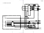
RF/Servo Block Diagram ............................................... 3-3
3-3.
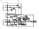
Signal Processor Block Diagram .................................. 3-5
3-4.
System Control Block Diagram ..................................... 3-7
3-5.
Video/Audio Block Diagram .......................................... 3-9
3-6.
Interface Control Block Diagram ................................... 3-11
3-7.
Power 1 Block Diagram ................................................. 3-13
3-8.
Power 2 Block Diagram ................................................. 3-15
4.
PRINTED WIRING BOARDS AND SCHEMATIC
DIAGRAMS
4-1.
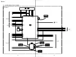
Frame Schematic Diagram ............................................ 4-3
4-2.
Printed Wiring Boards and Schematic Diagrams ......... 4-5
MB-103 Printed Wiring Board ....................................... 4-5
MB-103 (RF AMP, SERVO) Schematic Diagram .......... 4-9
MB-103 (ARP, SERVO DSP) Schematic Diagram ........ 4-11
MB-103 (AV DECODER) Schematic Diagram .............. 4-13
MB-103 (DRIVE) Schematic Diagram .......................... 4-15
MB-103 (SYSTEM CONTROL)
Schematic Diagram ....................................................... 4-17
MB-103 (CLOCK GENERATOR AUDIO D/A
CONVERTER) Schematic Diagram .............................. 4-19
AV-65 Printed Wiring Board .......................................... 4-21
AV-65 (AUDIO/VIDEO OUT) Schematic Diagram ........ 4-23
IF-95 Printed Wiring Board ........................................... 4-25
IF-95 (IF CON) Schematic Diagram ............................. 4-27
SW-370 (FUNCTION SWITCH) Printed Wiring Board
and Schematic Diagram ................................................ 4-29
SW-371 (DOOR SWITCH) Printed Wiring Board
and Schematic Diagram ................................................ 4-31
DPSN-20CP (SWITCHING REGULATOR)
Printed Wiring Board –US, CND– ................................. 4-32
DPSN-20CP (SWITCHING REGULATOR)
Schematic Diagram –US, CND– ................................... 4-33
DPSN-20CP-2 (SWITCHING REGULATOR)
Schematic Diagram –AEP, UK, E– ............................... 4-35
DPSN-20CP-2 (SWITCHING REGULATOR)
Printed Wiring Board –AEP, UK, E– .............................. 4-37
5.
IC PIN FUNCTION DESCRIPTION
5-1.
System Control Pin Function
(MB-103 Board IC104) .................................................. 5-1
6.
TEST MODE
6-1.
General Description ...................................................... 6-1
6-2.
Starting Test Mode ........................................................ 6-1
6-3.
Syscon Diagnosis .......................................................... 6-1
6-4.
Drive Auto Adjustment .................................................. 6-5
6-5.
Drive Manual Operation ................................................ 6-7
6-6.
Emergency History ........................................................ 6-10
6-7.
Version Information ....................................................... 6-11
6-8.
Video Level Adjustment ................................................ 6-11
6-9.
Troubleshooting ............................................................. 6-11
7.
ELECTRICAL ADJUSTMENT
7-1.
Power Supply Check ..................................................... 7-1
7-2.
Adjustment of Video System ......................................... 7-2
1.
Video Level Adjustment ................................................ 7-2
2.
Checking S Video Output S-Y ....................................... 7-2
3.
Checking S Video Output S-C ....................................... 7-2
7-3. Adjustment Related Parts Arrangement ....................... 7-4
8.
REPAIR PARTS LIST
8-1.
Exploded Views ............................................................. 8-1
8-1-1. Disk Base Section .................................................... 8-1
8-1-2. Lower Case Section ................................................. 8-2
8-2.
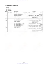
Electrical Parts List ....................................................... 8-3
www. xiaoyu163. com
QQ 376315150
9
9
2
8
9
4
2
9
8
TEL 13942296513
9
9
2
8
9
4
2
9
8
0
5
1
5
1
3
6
7
3
Q
Q
TEL 13942296513 QQ 376315150 892498299
TEL 13942296513 QQ 376315150 892498299


