23
Second Generation DVD
The second generation DVD players consist of models DVP-S300, DVP-
S500d, DVP-C600d, and DVP-S7700.
Symptom 1: No response to the Power ON button.
Cause: There are three common causes for this symptom.
1. A damaged power supply;
2. A short on another board that causes no power supply output voltage;
or
3. A defective front panel encoder (ref #165 in the DVP-S500d service
manual) preventing IC604 from reading the power ON button by lock-
ing up its program so the unit may not turn ON (intermittent turn ON).
Repair Procedure:
The power supply runs all the time when 120VAC is input, producing E
+5V. The +3.3V, +5V and +12V outputs are switched ON when the unit is
turned ON. You first need to determine if the basic power supply is defec-
tive.
1. Unplug the cable from the only connector on the power supply, CN201.
Look for E+5Vdc at CN201/pin 6 (alternate test point is at PS312)
from the power supply board. If there is no voltage, the power supply
is inoperative. The most common cause is a shorted main oscillator
MOSFET transistor, Q103, which has taken out the main fuse. Q103
P/N = 9-880-437-01 which is a 2SK2798 for the USA models.
If the new Q103 fails or there is still no output voltage, replace the
associated control parts Q101, Q102 and D104.
2. If the power supply does produce the E+5, the front panel rotary en-
coder or a short in another board is suspected. The encoder is at-
tached to a ribbon cable that plugs into CN103 of the front panel board.
Unplug the encoder, plug in the power supply cable and press the
power ON button to verify the defect.
3. If the unit still did not power up, you may leave the rotary encoder
cable detached while you look for the short circuit that is preventing
your unit from responding to the Power ON button. This is because
the front panel must be removed to reseat the encoder cable and it is
more important that you locate the problem. Either use your ohm
meter to locate a short at the power supply connector CN201 or re-
peatedly press the power button while monitoring the output voltages
to see which one is missing:
CN201/pin 1 =
+5.2Vdc
CN201/pin 2 = +5.2Vdc
CN201/pin 3 = Ground
CN201/pin 4 =
+3.3Vdc
CN201/pin 5 = Ground
CN201/pin 6 = E5.Vdc
CN201/pin 7 = Ground
CN201/pin 8 = P Cont (input)
CN201/pin 9 = AU +12Vdc
CN201/pin 10 = AU Ground
CN201/pin 11 =
AU –12Vdc
CN201/pin 12 = -12Vdc
CN201/pin 13 = Ground
CN201/pin 14 =
Motor +12Vdc
CN201/pin 12 = Motor Ground
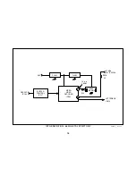
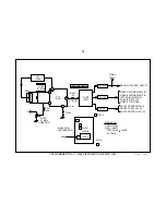
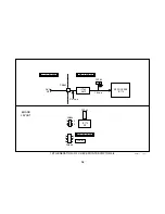
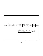
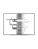
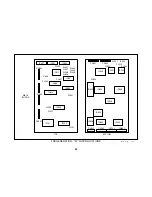
Use the +3.3V and 5V distribution diagrams in this book (symptom 2) to
locate the shorted IC.
Summary of Contents for DVP-S300
Page 4: ...1 NOTES ...
Page 13: ...10 NOTES ...
Page 19: ...16 NOTES ...
Page 25: ...22 NOTES ...
Page 29: ...26 NOTES ...
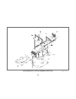
Page 35: ...32 2ND GENERATION OPTICAL ASSEMBLY SYMPTOM 3 1 3 01 19DVD03 ...
Page 39: ...36 NOTES ...
Page 61: ...58 Flex Cable DVP C650 ...
Page 71: ...68 NOTES ...
Page 76: ...APPENDIX ...

