6-2
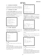
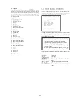
Selecting 2 and subsequent items executes respective menus and
outputs the results.
For the contents of each submenu, see “Check Items List”.
General Description of Checking Method
2.
Version
(2-2) Revision
ROM revision number is displayed.
Error: Not detected.
The revision number defined in the source file of ROM
(IC206) is displayed with four digits.
(2-3) ROM Check Sum
Check sum is calculated.
Error: Not detected.
The 8-bit data are added at addresses 0x000F0000 ~
0x002EFFFF of ROM (IC206) and the result is displayed
with 4-digit hexadecimal number. Error is not detected.
Compare the result with the specified value.
(2-4) Model Type
Model code is displayed.
Error: Not detected.
The model code read from EEPROM (IC201) is displayed
with 2-digit hexadecimal number.
Model Type
DVP-S320 (Singapore)
0
3
(2-5) Region
Region code is displayed.
Error: Not detected.
The region code determined from the model code is dis-
played.
3.
Peripheral
(3-2) Gate Array Check
Data write
→
read, and accord check
Error 02: Gate array write/read discord
Data 0x00~0xFF are written to the address 0xF of GA
(IC601), then read and checked if they accord.
(3-3) EEPROM Check
Data write
→
read, and accord check
Error 03: EEPROM write/read discord
Data 0x9249, 0x2942, 0x4294 are written to addresses
0x00~0xFF of EEPROM (IC201), then read and checked.
Before writing, the data are saved, then after checking, they
are written to restore the contents of EEPROM.
4.
Servo
(4-2) Servo DSP Check
Data write
→
read, and accord check
Error 12: Read data discord
Data 0x9249, 0x2942, 0x4294 are written to the address
0x602 of RAM in the Servo DSP (IC701), then read and
checked.
(4-3) DSP Driver Test
Test signal data
→
DSP Driver
Error: Not detected.
Caution: Do not conduct this test with a mechanical deck
connected.
The maximum voltage is applied to the Servo Driver IC
(IC801, IC802). If mechanical deck is connected, the mo-
tor and optics could be damaged. Disconnect mechanical
deck following the output message, then enter specified 4-
or 5-digit number from the remote commander, and press
the
[ENTER]
. The test is conducted only when the input
data accord. Check the output level, then press the
[NEXT]
to finish the test.
This test is skipped if “All” is selected.
Supplement: How to disconnect mechanical deck
Disconnect flat cables connected to the CN002
and CN003 of MB-82 board. Also, disconnect
harness from the CN011.
5.
Supply
Caution: Do not conduct this check with a mechanical deck con-
nected.
An access is made to the stream supply and servo con-
trol IC (IC303) and external RAM (IC304) using check
data. If mechanical deck is connected, the motor and
optics could be damaged. This check is also executed by
the “All” menu item.
Supplement: How to disconnect mechanical deck
Disconnect flat cables connected to the CN002 and
CN003 of MB-82 board. Also, disconnect harness
from the CN011.
(5-2) ARP Register Check
Data write
→
read, and accord check
Error 08: ARP register write, and read data discord
Data 0x00 to 0xFF are written to the TMAX register (ad-
dress 0xC6) in ARP (IC303), then they are read and checked.
(5-3) ARP to RAM Data Bus
Data write
→
read, and accord check
Error 09: ARP
←→
RAM data bus error
Data 0x0001 to 0x8000 where one bit each is set to 1 are
written to the address 0 of RAM (IC304) connected to the
ARP (IC303) through the bus, then they are read and
checked. In case of discord, written bit pattern and read
data are displayed. If data where multiple bits are 1 are
read, the bits concerned may touch each other. Further, if
data where certain bit is always 1 or 0 regardless of written
data, the line could be disconnected or shorted.
Summary of Contents for DVP-S320
Page 6: ...1 1 SECTION 1 GENERAL This section is extracted from instruction manual 3 867 036 11 DVP S320 ...
Page 7: ...1 2 ...
Page 8: ...1 3 ...
Page 9: ...1 4 ...
Page 10: ...1 5 ...
Page 11: ...1 6 ...
Page 12: ...1 7 ...
Page 13: ...1 8 ...
Page 14: ...1 9 ...
Page 15: ...1 10 ...
Page 16: ...1 11 ...
Page 17: ...1 12 ...
Page 18: ...1 13 ...
Page 19: ...1 14 1 14 E ...
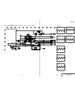
Page 33: ...DVP S320 FRAME 1 2 4 3 4 4 4 1 FRAME SCHEMATIC DIAGRAM FRAME 1 SCHEMATIC DIAGRAM ...
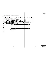
Page 34: ...DVP S320 4 5 4 6 FRAME 2 SCHEMATIC DIAGRAM FRAME 2 2 ...


