8-1
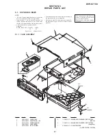
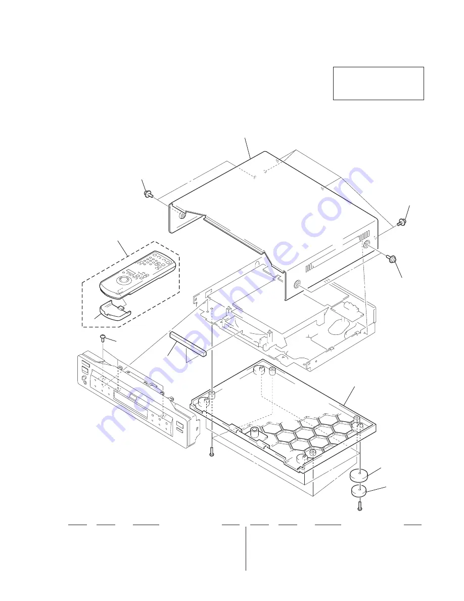
8-1-1. CASE ASSEMBLY
Ref. No.
Part No.
Description
Remark
Ref. No.
Part No.
Description
Remark
1
2
7
6
3
3
3
4
not
supplied
not
supplied
#2
#1
5
NOTE:
• -XX and -X mean standardized parts, so they may
have some difference from the original one.
• Items marked “*” are not stocked since they are
seldom required for routine service. Some delay
should be anticipated when ordering these items.
• Color Indication of Appearance Parts
Example:
KNOB, BALANCE (WHITE) . . . (RED)
↑
↑
Parts Color
Cabinet's Color
• The mechanical parts with no reference number in
the exploded views are not supplied.
• Hardware (# mark) list and accessories and pack-
ing materials are given in the last of the electrical
parts list.
SECTION 8
REPAIR PARTS LIST
8-1.
EXPLODED VIEWS
DVP-S7700
The components identified by
mark
!
or dotted line with mark
!
are critical for safety.
Replace only with part number
specified.
6
1-418-075-31 COMMANDER, STANDARD (RMT-D107P/N)
(AEP, UK)
6
1-418-075-41 COMMANDER, STANDARD (RMT-D107E/N)
(Hong Kong)
7
3-709-044-31 LID, BATTERY CASE
(for RMT-D107E/N, D107P/N)
1
3-052-655-11 COVER, TRAY
2
3-970-608-11 SUMITITE (B3), +BV
3
3-710-901-51 SCREW, TAPPING
4
3-052-658-11 CASE, UPPER
5
4-970-487-01 FOOT (F50180S)
Summary of Contents for DVP-S7700
Page 12: ...1 2 ...
Page 13: ...1 3 ...
Page 14: ...1 4 ...
Page 15: ...1 5 ...
Page 16: ...1 6 ...
Page 17: ...1 7 ...
Page 18: ...1 8 ...
Page 19: ...1 9 ...
Page 20: ...1 10 ...
Page 21: ...1 11 1 11 E ...
Page 36: ...DVP S7700 4 3 4 4 4 1 FRAME SCHEMATIC DIAGRAM 1 2 FRAME 1 2 ...
Page 37: ...DVP S7700 4 5 4 6 FRAME SCHEMATIC DIAGRAM 2 2 FRAME 2 2 ...


