background image

1-11

1-11 E

Summary of Contents for DVP-S7700

Page 1: ...MICROFILM SERVICE MANUAL AEP Model Hong Kong Model UK Model CD DVD PLAYER DVP S7700 RMT D107E D107P SPECIFICATIONS ...

Page 2: ...SONY PARTS WHOSE PART NUMBERS APPEAR AS SHOWN IN THIS MANUAL OR IN SUPPLEMENTS PUB LISHED BY SONY 1 Check the area of your repair for unsoldered or poorly sol dered connections Check the entire board surface for solder splashes and bridges 2 Check the interboard wiring to ensure that no wires are pinched or contact high wattage resistors 3 Look for unauthorized replacement parts particularly trans...

Page 3: ...5 YS 19 Printed Wiring Board and Schematic Diagram 4 57 ER 8 Printed Wiring Board 4 59 ER 8 EURO AV 1 Schematic Diagram 4 63 ER 8 EURO AV 2 Schematic Diagram 4 65 ER 8 EURO AV 3 Schematic Diagram 4 67 HP 120 Printed Wiring Board and Schematic Diagram 4 69 FP 75 Printed Wiring Board 4 71 FP 75 Schematic Diagram 4 73 CN 113 DR 88 FL 108 FR 160 PW 120 Printed Wiring Boards 4 75 CN 113 DR 88 FL 108 FR...

Page 4: ...Page 2 2 TK 47 Board Page 2 2 Upper Case Page 2 1 MB 84 Board Page 2 1 Front Panel Section Page 2 1 Door Open Close Motor Page 2 1 AU 218 Board Page 2 2 MD Block Ass y Page 2 2 Optical Pick up Page 2 3 Skew Motor Page 2 3 Spindle Base Page 2 3 Sled Motor Page 2 3 Spindle Motor Page 2 3 Set ...

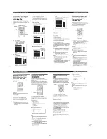
Page 5: ... in direction B by 1 4 turn 2 Draw out the tray 3 in direction C by hand and remove a disk See Fig 2 Fig 2 1 Gear D A B C 2 Cam gear 3 Tray Hole 3 HOW TO SERVICE MB 84 SIDE B BOARD 1 Remove the case from the set Refer to 2 1 2 Remove the cover upper Refer to 2 3 3 Set the MB 84 board as shown in Fig 3 Note 1 Do not disconnect wiring Note 2 Spread a insulating material under the MB 84 board and thr...

Page 6: ...e MD block ass y 3 90 º with the side down confirm that the optical pick up 4 falls by self weight See Fig 5 4 Further with the front side of MD block ass y 3 up confirm that the optical pick up falls by self weight Fig 5 1 Sled motor ass y 2 Two screws M1 7 2 5 A 3 MD block ass y 4 Optical pick up Upper Lower Front side Upper Lower Front side ...

Page 7: ...parts the short lands have been soldered to protect from static electricity Accordingly remove solders when replacing opti cal pick up See Fig 6 Fig 6 Flexible board 3 In handling the KHS 180A RP do not touch inhibited parts shown in Fig 7 but grip the slide base bearing and U shaped guide Fig 7 KHS 180A RP DVD short land CD short land Slide base bearing Skew sensor Lens actuator covers Objective ...

Page 8: ...nded grease is Foil KG 70MP Note 2 In applying grease take care not to allow grease to stick to other parts particularly rubber belt spindle motor and optical pick up Base unit holder 2 bosses Slide base Skew cam Cam gear Tray 3 grooves Note Add grease if tray moves slowly Loading pulley shaft Note Add grease if tray generates noise periodically Fig 8 ...

Page 9: ...unction normally if the board floats up Fig 12 6 2 Cleaning Spindle Motor Turntable 1 Remove the tray Refer to 2 7 2 Clean the spindle motor turntable if disc antiskid rubber black is dirty See Fig 9 Fig 9 6 3 Aligning Phase of Cam Gear and Drive Gear 1 Align triangle marks when assembling the cam gear and drive gear See Fig 10 Fig 10 Spindle motor Turntable Drive gear Cam gear Align triangle mark...

Page 10: ...screws BV3 10 The sensor will not function normally if the board floats up Fig 13 6 7 Note on connecting OPT Harness 1 The optical pick up could be destroyed unless the OPT har ness is connected normally to the connector See Fig 14 Fig 14 TK 47 board Three screws BV3 10 Two claws Boss Two claws Boss OPT harness Connector Good NG ...

Page 11: ...1 1 SECTION 1 GENERAL DVP S7700 This section is extracted from AEP UK model instruction manual 3 864 941 31 ...

Page 12: ...1 2 ...

Page 13: ...1 3 ...

Page 14: ...1 4 ...

Page 15: ...1 5 ...

Page 16: ...1 6 ...

Page 17: ...1 7 ...

Page 18: ...1 8 ...

Page 19: ...1 9 ...

Page 20: ...1 10 ...

Page 21: ...1 11 1 11 E ...

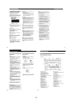
Page 22: ...ng screws 4 Upper case 2 Four tapping screws 3 Two tapping screws 4 claw 3 Three screws B3 2 Connector CN002 1 Font cable CN601 6 Claw 5 Claw 7 Front panel 1 Flat cable CN451 2 Two screws PS3 4 3 Door open close motor CN 112 board 1 Two connectors CN001 002 4 Connector CN361 5 Two screws B3 3 Flat cable CN251 2 Two flat cables CN301 601 6 Three screws B3 7 Cover upper 8 MB 84 board 9 Four flat cab...

Page 23: ...wo screws B3 2 Copper leaf plate 5 Flat cable CN202 AEP UK 1 Cover lower 7 MD block ass y 4 Two screws B3 2 Two screws B3 6 Clamp 5 Two screws B3 3 Chassis bracket B 2 Flat cable spindle motor CN002 1 Connector CN004 5 Two claws 3 OP 15 flexible board CN001 4 Four screws BVTP3 10 6 TK 47 board A 3 Rotate the cam gear in direction A 5 Claw 6 Remove the tray 4 Pull the tray 2 Press pully bracket 1 T...

Page 24: ...L 2 Claw 4 Skew motor M903 3 Skew gear retainer 1 Screw PT WH2 5 1 OP 15 flexible board CN001 3 Skew shaft stopper 2 Screw P2 8 7 Sled motor M501 5 Screw PTTWH2 5 6 Two screws P1 7 2 5 4 Spindle base 1 Three screws PTTWH2 5 2 Spindle motor M901 1 OP 15 flexible board CN001 2 Screw PTTWH2 5 3 Main shaft 4 Optical pick up ...

Page 25: ...180A J1N 8 820 005 02 Skew motor ass y tilt X 3947 138 1 Sled motor ass y X 3947 137 1 DC motor spindle 1 698 944 11 Sled motor ass y X 3947 137 1 Optical pick up KHS 180A J1N 8 820 005 02 Motor loading 1 698 942 21 DC motor spindle 1 698 944 11 ...

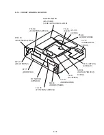
Page 26: ...MB 84 SIGNAL PROCESS SERVO HP 120 HEAD PHONE PW 120 IR POWER SWITCH FR 160 FUNCTION SWITCH DC MOTOR SPINDLE DR 88 DOOR SENSOR CN 113 DOOR MOTOR TK 47 RF SERVO YS 19 COMPONENT VIDEO AU 218 AUDIO FG 43 SLED PS 421 AUDIO POWER FP 75 FL DRIVER FL 108 FUNCTION SWITCH ER 8 AEP UK EURO AV ...

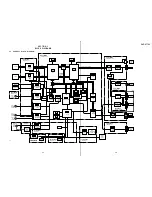
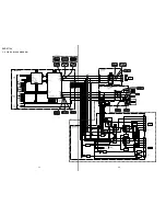
Page 27: ...C506 SERVO DSP IC804 1 2 LGATE ARRAY IC807 S GATE ARRAY IC802 1M SRAM YC0 7 IC804 2 2 L GATE ARRAY IC801 EEPROM IC803 8M ROM IC806 ARP IC810 16M DRAM IC203 AV DECODER IC201 202 16M SRAM SPDIF AV_DATA AV_BLK AV_LRCK IC204 AUDIO 2CH DAC IC209 VIDEO BUFFER AUDIO PHONE COMPONENT VIDEO VIDEO S VIDEO DIGITAL OUT IC206 207 FILTER AMP BUFFER IC208 BUFFER IC001 HP AMP IC207 OSD IC252 VIDEO ENCODER IC251 DN...

Page 28: ... 32 2 5 33 34 29 30 22 23 Q371 MUTE Q372 MUTE IC363 IC303 IC301 SPINDLE MOTOR DRIVER IC302 SLED MOTOR DRIVER 19 20 3 5 65 79 3 98 4 100 71 70 84 94 56 ı 63 28 37 42 45 50 36 43 44 51 M901 SPINDLE MOTOR TIMT SLDMT CN501 CN301 CN361 HA HB SLVH DOUT1 8 9 DOUT2 IN1 MUTE1 CD FCS CD TRK DVD FCS DVD TRK U IN V IN W IN SPVH U OUT V OUT W OUT U IN V IN W IN SPVH U OUT V OUT W OUT APC_ON Q009 VC VC VC VC DV...

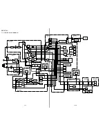
Page 29: ...Q AVCS AVINT AVWT MRST RF SERVO SEE PAGE 3 3 4 SYSTEM CONTROL SEE PAGE 3 9 10 IA0 7 ID0 7 IA0 8 ID0 7 SD0 7 SD0 7 DCRSD0 7 AREQ ALALID ERROR TOS DTI0 7 DTO0 7 SDCK XSHD XSRO XSAK SDEF CD_LRCK CD_BCK CD_DATA SPDIF 54 51 28 111 105 106 107 SYSTEM CONTROL SEE PAGE 3 9 10 CGCSO CS IC201 16M SDRAM AVA0 11 AVID 0 15 IC202 16M SDRAM SDQM WE CAS RAS CS1 CS2 SDQM SDCLK A_0 8 D_0 7 21 24 26 30 98 99 101 102...

Page 30: ...GR YUY_RGB E_V Y AVCNT E_V RGB YUV_RGB MRST VCS RV251 VIDEO LEVEL ADJ 11 ı 18 60 ı 67 51 ı 58 MRST DCS 27M_DNR OHSYNC SCKG3 SOG3 DCS Hong Kong Hong Kong Q218 BIFFER AEP UK 1 3 9 YUV_RGB AEP UK E_V RGB AV_CONT EURO_V Y V MUTE Hong Kong 8 V MUTE 2 8 IC252 IC252 IC252 IC252 0 7 Vp p 1 0 Vp p IC252 1 0 Vp p IC252 IC851 0 1 0 Vp p H IC851 0 7 Vp p H IC209 1 1 Vp p H IC209 0 0 7 Vp p H IC209 1 0 Vp p H ...

Page 31: ...SDEN SPCTRL1 DVDLDON CDLDON TILT H SSSD SCKG3 SCKG3 SOG3 D2LT SPCTRL0 SPGC2 SPGC1 S12VOFF FON S12VOFF SDSPRD SDSPWR BUSY2 ERROR TRAY_FREE NST CD DVD AVWT AVCS DCRWT DCRINT DCRCS IWR IRD ARPWT ARPCS ARPINT MUTE MD2 DFCT NORF LOCK FWON OHSYNC XIFBSY IFSI IFSO DIAG XSHINT AVWT AVCS DCRWT DCRINT DCRCS XWR XRD ARPWT ARPCS ARPINT VCS SOG3 SCKG3 OHSYNC 49 DOUTCTL HSYNC 13 5M AVCK SOG2 VSI VS VCS A MUTE M...

Page 32: ...0 17 19 18 16 5 CN252 2 2 4 5 3 1 8 CN101 22 21 23 25 18 6 9 7 8 10 21 CN201 2 2 CN203 D2LT SOG3 MRST IC208 POWER SEE PAGE 3 15 PFAIL RSTB PMUTE AUDIO MUTE MA MUTE AMUTE SCKG3 D2LT SOG3 AV_LRCK AV_BCK AV_DATA DOUTCTL 384FS 2CH SPDIF MODE CONTROL SEE PAGE 3 13 SYSTEM CONTROL SEE PAGE 3 9 SIGNAL PROCESS SEE PAGE 3 6 SYSTEM CONTROL SEE PAGE 3 9 10 MB 84 BOARD 5 6 SEE PAGE 4 21 4 23 MRST 1 5 7 3 1 5 2...

Page 33: ...E PAGE 3 9 10 S404 S403 S402 S159 S157 DVD MENU S155 S401 SEP UP DNR PREV NEXT TITLE D201 AD6 AD4 AD3 AD3 IR IR DTS IC605 RESET IC606 COMP IC 201 FL DRIVER IC301 REMOTE CONTROL RECEIVER ON STANDBY D303 IC603 IC604 I F µ COM IC601 ROM ALE OE WE A00 019 AD00 07 LATCH S160 OPEN CLOSE S158 PANEL S156 ENTER S154 RIGHT S153 UP S152 S151 LEFT S301 POWER DOWN CN601 CN153 10 11 12 13 SI SCKL FLCS BZ 10 11 ...

Page 34: ... 11 6 6 17 1 CN601 IC601 IC602 IC603 IC604 IC605 IC606 IC204 IC205 IC206 IC207 IC209 IC252 IC251 IC812 LPF Q001 002 SWITCH IC801 IC803 IC804 IC805 IC807 IC811 IC802 IC301 IC452 IC455 IC501 IC502 IC503 IC506 IC507 IC508 IC363 F001 IC361 F002 IC302 IC303 F003 F004 S12V OFF SYSTEM CONTROL SEE PAGE 3 9 IC806 IC201 IC202 IC203 IC208 IC810 CN153 CN151 CN102 IC151 F151 ND201 F F CN154 CN301 IC301 Q301 IC...

Page 35: ...se noted pF µµF 50V or less are not indicated except for electrolytics and tantalums All variable and adjustable resistors have characteristic curve B unless otherwise noted 2 nonflammable resistor 5 fusible resistor C panel designation internal component C adjustment for repair U B Line V B Line Circled numbers refer to waveforms Voltages are dc between measurement point Readings are taken with a...

Page 36: ...DVP S7700 4 3 4 4 4 1 FRAME SCHEMATIC DIAGRAM 1 2 FRAME 1 2 ...

Page 37: ...DVP S7700 4 5 4 6 FRAME SCHEMATIC DIAGRAM 2 2 FRAME 2 2 ...

Page 38: ...SCHEMATIC DIAGRAMS TK 47 RF SERVO PRINTED WIRING BOARD Ref No TK 47 board 3 000 series RF SERVO TK 47 POWER BLOCK HS 930SH SWITCHING REGULATOR MB 84 SIGNAL PROCESS SERVO HP 120 HEAD PHONE PW 120 IR POWER SWITCH FR 160 FUNCTION SWITCH DC MOTOR SPINDLE DR 88 DOOR SENSOR CN 113 DOOR MOTOR TK 47 RF SERVO YS 19 COMPONENT VIDEO AU 218 AUDIO FG 43 SLED PS 421 AUDIO POWER FP 75 FL DRIVER FL 108 FUNCTION S...

Page 39: ...DVP S7700 4 9 RF SERVO TK 47 DVP S7700 1 669 298 05 13 13 TK 47 BOARD SIDE B A B C D E F G H 1 2 3 4 5 6 ...

Page 40: ...270 mVp p V 2 IC006 DVD play 1 2 Vp p V 3 IC006 DVD play 800 mVp p V 4 IC005 CD play 500 mV DIV 1 ms DIV 5 IC005 CD play 500 mV DIV 10 ms DIV 6 IC005 CD play 500 mV DIV 1 µs DIV Note The components identified by mark or dotted line with mark are critical for safety Replace only with part number specified DVD_FE D006 MA151WA TX R018 22k ...

Page 41: ...DVP S7700 4 13 4 14 TK 47 RF SERVO 2 SCHEMATIC DIAGRAM Ref No TK 47 board 3 000 series RF SERVO 2 TK 47 2 2 ...
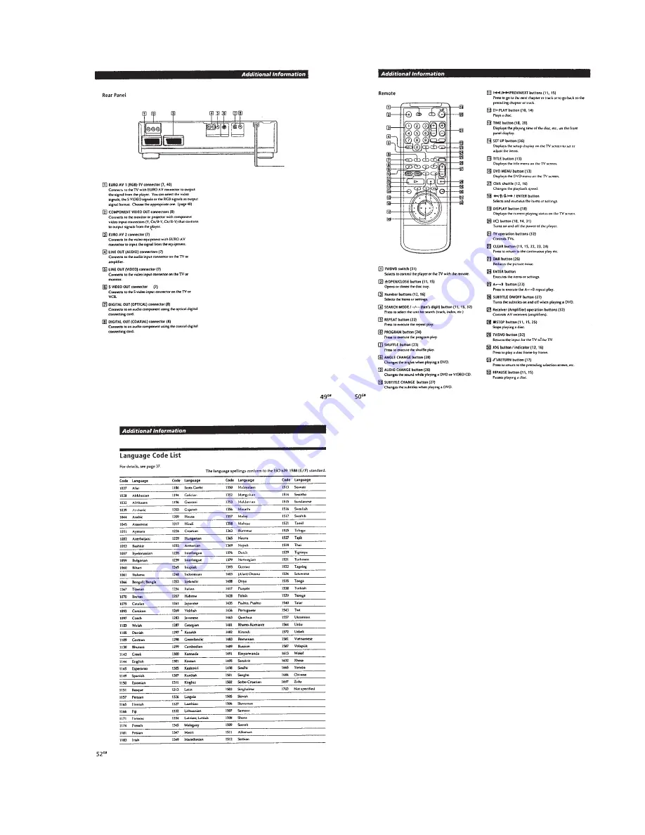
Page 42: ...04 E 6 IC805 E 3 IC806 B 4 Q371 C 3 Q372 C 4 Q501 A 5 There are few cases that the part isn t mounted in this model is printed on this diagram SIGNAL PROCESS SLED MB 84 FG 43 POWER BLOCK HS 930SH SWITCHING REGULATOR MB 84 SIGNAL PROCESS SERVO HP 120 HEAD PHONE PW 120 IR POWER SWITCH FR 160 FUNCTION SWITCH DC MOTOR SPINDLE DR 88 DOOR SENSOR CN 113 DOOR MOTOR TK 47 RF SERVO YS 19 COMPONENT VIDEO AU ...

Page 43: ...04 B 6 IC207 B 7 IC208 C 7 IC209 D 2 IC302 B 2 IC361 C 2 IC363 C 5 IC452 A 4 IC502 B 4 IC503 B 4 IC507 C 4 IC601 F 2 IC602 F 3 IC605 E 2 IC606 F 1 IC801 E 3 IC802 F 4 IC807 F 6 IC810 B 5 IC811 D 7 IC812 B 6 Q001 E 7 Q002 E 7 Q452 C 5 SIGNAL PROCESS MB 84 1 24 25 40 41 64 65 80 1 671 899 05 11 MB 84 BOARD SIDE B A B C 1 2 3 4 5 6 7 8 D E F 1 7 1 8 R834 13 1 14 25 R911 1 2 2 1 ...
Page 44: ...DVP S7700 4 19 4 20 MB 84 AV DECODER SCHEMATIC DIAGRAM See page 4 15 to 4 18 for printed wiring board Ref No MB 84 board 2 000 series AV DECODER MB 84 1 14 ...

Page 45: ...1 4 22 MB 84 CLOCK GENERATOR SCHEMATIC DIAGRAM See page 4 15 to 4 18 for printed wiring board Ref No MB 84 board 2 000 series Waveforms 1 IC206 8 3 28 Vp p 27 MHz 2 IC209 1 1 4 Vp p 27 MHz CLOCK GENERATOR MB 84 2 14 ...

Page 46: ...DVP S7700 4 23 4 24 MB 84 DNR SCHEMATIC DIAGRAM See page 4 15 to 4 18 for printed wiring board Ref No MB 84 board 2 000 series DNR MB 84 3 14 ...

Page 47: ...H 2 IC252 AEP UK model RGB output mode 0 7 Vp p H 3 IC252 0 7 Vp p H 3 IC252 AEP UK model RGB output mode 0 7 Vp p H 4 IC252 1 0 Vp p H 5 IC252 0 7 Vp p H 6 IC252 1 1 Vp p H MB 84 VIDEO ENCODER SCHEMATIC DIAGRAM See page 4 15 to 4 18 for printed wiring board Ref No MB 84 board 2 000 series VIDEO ENCODER MB 84 4 14 ...

Page 48: ...7 4 28 MB 84 DRIVE 1 SCHEMATIC DIAGRAM See page 4 15 to 4 18 for printed wiring board Ref No MB 84 board 2 000 series DRIVE 1 MB 84 5 14 Waveforms 1 IC303 ª DVD play 5 2 Vp p 160 Hz 2 IC303 ª CD play 1 84 Vp p 45 Hz ...

Page 49: ...DVP S7700 4 29 4 30 DRIVE 2 SLED MB 84 6 14 FG 43 MB 84 DRIVE 2 FG 43 SLED SCHEMATIC DIAGRAMS See page 4 15 to 4 18 for printed wiring boards Ref No MB 84 board 2 000 series FG 43 board 1 000 series ...

Page 50: ...DVP S7700 4 31 4 32 MB 84 DSP 1 SCHEMATIC DIAGRAM See page 4 15 to 4 18 for printed wiring board Ref No MB 84 board 2 000 series DSP 1 MB 84 7 14 ...

Page 51: ...DVP S7700 4 33 4 34 Waveform 1 IC506 3 6 Vp p 27 MHz MB 84 DSP 2 SCHEMATIC DIAGRAM See page 4 15 to 4 18 for printed wiring board Ref No MB 84 board 2 000 series DSP 2 MB 84 8 14 ...

Page 52: ...MATIC DIAGRAM See page 4 15 to 4 18 for printed wiring board Ref No MB 84 boards 2 000 series BIAS MB 84 9 14 Note The components identified by mark or dotted line with mark are critical for safety Replace only with part number specified ...

Page 53: ...DVP S7700 4 37 4 38 MB 84 IF µ COM SCHEMATIC DIAGRAM See page 4 15 to 4 18 for printed wiring board Ref No MB 84 board 2 000 series IF µ COM MB 84 10 14 Waveform 1 IC604 5 6 Vp p 4 MHz ...

Page 54: ...2 IC804 fi 3 3 Vp p 27 MHz 3 IC806 0 1 5 Vp p 4 IC806 3 0 Vp p 33 MHz 5 IC806 3 4 Vp p 27 MHz 6 IC811 3 4 Vp p 27 MHz L GATE ARRAY MB 84 11 14 MB 84 L GATE ARRAY SCHEMATIC DIAGRAM See page 4 15 to 4 18 for printed wiring board Ref No MB 84 board 2 000 series ...

Page 55: ...DVP S7700 4 41 4 42 ARP DECRYPT MB 84 12 14 MB 84 ARP DECRYPT SCHEMATIC DIAGRAM See page 4 15 to 4 18 for printed wiring board Ref No MB 84 board 2 000 series ...

Page 56: ...DVP S7700 4 43 4 44 MB 84 SYSTEM µ COM SCHEMATIC DIAGRAM See page 4 15 to 4 18 for printed wiring board Ref No MB 84 board 2 000 series SYSTEM µ COM MB 84 13 14 ...

Page 57: ...DVP S7700 4 45 4 46 S GATE ARRAY MB 84 14 14 MB 84 S GATE ARRAY SCHEMATIC DIAGRAM See page 4 15 to 4 18 for printed wiring board Ref No MB 84 board 2 000 series Waveform 1 IC805 4 4 Vp p 20 MHz ...

Page 58: ... this diagram POWER BLOCK HS 930SH SWITCHING REGULATOR MB 84 SIGNAL PROCESS SERVO HP 120 HEAD PHONE PW 120 IR POWER SWITCH FR 160 FUNCTION SWITCH DC MOTOR SPINDLE DR 88 DOOR SENSOR CN 113 DOOR MOTOR TK 47 RF SERVO YS 19 COMPONENT VIDEO AU 218 AUDIO FG 43 SLED PS 421 AUDIO POWER FP 75 FL DRIVER FL 108 FUNCTION SWITCH ER 8 AEP UK EURO AV 1 671 910 05 11 11 AU 218 BOARD SIDE A ...

Page 59: ...11 B 8 D214 A 9 D216 A 7 IC202 B 8 IC204 C 6 IC205 A 8 IC206 B 7 IC207 B 4 IC208 B 1 IC209 B 2 IC210 A 2 Q201 B 8 Q202 A 9 Q203 B 5 Q204 B 6 Q205 B 8 Q206 A 10 Q207 A 10 Q208 A 10 Q209 B 7 Q210 B 7 Q211 B 5 Q212 B 6 Q213 A 7 Q214 B 3 Q215 B 3 Q216 A 1 Q217 B 7 Q218 C 4 1 671 910 05 11 11 AU 218 BOARD SIDE B A 1 2 3 4 5 6 7 8 9 B C COAXIAL DIGITAL OUT OPTICAL S VIDEO OUT VIDEO L R AUDIO LINE OUT ...

Page 60: ...DVP S7700 4 51 4 52 AUDIO 1 AU 218 1 3 AU 218 AUDIO 1 SCHEMATIC DIAGRAM See page 4 47 to 4 50 for printed wiring board Ref No AU 218 board 3 000 series ...

Page 61: ...DVP S7700 4 53 4 54 AUDIO 2 AU 218 2 3 AU 218 AUDIO 2 SCHEMATIC DIAGRAM See page 4 47 to 4 50 for printed wiring board Ref No AU 218 board 3 000 series ...

Page 62: ... 4 56 VIDEO BUFFER AU 218 3 3 AU 218 VIDEO BUFFER SCHEMATIC DIAGRAM See page 4 47 to 4 50 for printed wiring board Ref No AU 218 board 3 000 series Waveforms 1 IC209 1 1 Vp p H 2 IC209 1 0 Vp p H 3 IC209 0 0 7 Vp p H ...

Page 63: ...CESS SERVO HP 120 HEAD PHONE PW 120 IR POWER SWITCH FR 160 FUNCTION SWITCH DC MOTOR SPINDLE DR 88 DOOR SENSOR CN 113 DOOR MOTOR TK 47 RF SERVO YS 19 COMPONENT VIDEO AU 218 AUDIO FG 43 SLED PS 421 AUDIO POWER FP 75 FL DRIVER FL 108 FUNCTION SWITCH ER 8 AEP UK EURO AV There are few cases that the part isn t mounted in this model is printed on this diagram 1 671 915 11 11 YS 19 BOARD SIDE A 05 1 671 ...

Page 64: ...08 A 5 D609 A 6 D610 A 6 D616 A 2 D617 A 3 D618 A 3 D619 A 3 D620 A 4 D622 A 2 D623 A 2 D625 C 4 D626 C 2 D627 C 5 D628 B 2 D633 C 3 D634 C 3 IC603 B 2 IC604 B 4 IC607 B 3 IC608 B 5 Q601 C 4 Q602 C 6 Q604 B 4 Q605 B 4 Q607 A 4 Q608 B 4 Q612 C 5 Q614 A 5 Q615 B 5 Q622 B 5 Q623 B 5 Q625 A 5 Q626 B 5 Q633 A 6 Q634 B 6 Q635 C 5 Q636 A 4 Q637 C 5 Q638 C 4 Q639 C 4 Q643 C 3 Q644 C 3 ER 8 EURO AV PRINTED...

Page 65: ...612 A 6 D613 A 5 D614 A 5 D615 A 4 D621 A 2 D624 A 3 D631 B 5 D632 B 4 D635 D 5 D636 D 5 IC601 C 5 IC602 B 4 Q606 C 1 Q621 C 3 Q624 C 3 Q627 C 2 Q628 B 5 Q629 B 4 Q630 C 2 Q632 C 2 Q640 C 2 Q641 C 1 Q642 D 5 EURO AV ER 8 2 20 21 1 2 21 20 1 671 916 05 11 11 ER 8 BOARD SIDE B A B C D 1 2 3 4 5 6 1 1 2 9 EURO AV2 EURO AV1 RGB TV 2 1 9 ...

Page 66: ...DVP S7700 4 63 4 64 EURO AV 1 ER 8 1 3 ER 8 EURO AV 1 SCHEMATIC DIAGRAM See page 4 59 to 4 62 for printed wiring board Ref No ER 8 board 1 000 series AEP UK ...

Page 67: ...DVP S7700 4 65 4 66 EURO AV 2 ER 8 2 3 ER 8 EURO AV 2 SCHEMATIC DIAGRAM See page 4 59 to 4 62 for printed wiring board Ref No ER 8 board 1 000 series AEP UK ...

Page 68: ...DVP S7700 4 67 4 68 ER 8 EURO AV 3 SCHEMATIC DIAGRAM See page 4 59 to 4 62 for printed wiring board Ref No ER 8 board 1 000 series AEP UK EURO AV 3 ER 8 3 3 ...

Page 69: ...0SH SWITCHING REGULATOR MB 84 SIGNAL PROCESS SERVO HP 120 HEAD PHONE PW 120 IR POWER SWITCH FR 160 FUNCTION SWITCH DC MOTOR SPINDLE DR 88 DOOR SENSOR CN 113 DOOR MOTOR TK 47 RF SERVO YS 19 COMPONENT VIDEO AU 218 AUDIO FG 43 SLED PS 421 AUDIO POWER FP 75 FL DRIVER FL 108 FUNCTION SWITCH ER 8 AEP UK EURO AV HEAD PHONE HP 120 1 671 918 12 12 HP 120 BOARD SIDE A 05 1 671 918 12 12 HP 120 BOARD SIDE B ...

Page 70: ... PROCESS SERVO HP 120 HEAD PHONE PW 120 IR POWER SWITCH FR 160 FUNCTION SWITCH DC MOTOR SPINDLE DR 88 DOOR SENSOR CN 113 DOOR MOTOR TK 47 RF SERVO YS 19 COMPONENT VIDEO AU 218 AUDIO FG 43 SLED PS 421 AUDIO POWER FP 75 FL DRIVER FL 108 FUNCTION SWITCH ER 8 AEP UK EURO AV There are few cases that the part isn t mounted in this model is printed on this diagram 1 671 913 05 11 11 FP 75 BOARD SIDE A A ...

Page 71: ...DVP S7700 4 73 4 74 FP 75 FL DRIVER SCHEMATIC DIAGRAM Ref No FP 75 board 1 000 series FL DRIVER FP 75 ...

Page 72: ...R CN 113 DOOR MOTOR TK 47 RF SERVO YS 19 COMPONENT VIDEO AU 218 AUDIO FG 43 SLED PS 421 AUDIO POWER FP 75 FL DRIVER FL 108 FUNCTION SWITCH ER 8 AEP UK EURO AV There are few cases that the part isn t mounted in this model is printed on this diagram 1 671 914 11 11 PW 120 BOARD SIDE A 05 ON STANDBY 1 671 914 11 11 PW 120 BOARD SIDE B 05 POWER 1 671 911 05 11 11 FL 108 BOARD SIDE A A B 1 2 3 4 5 1 67...

Page 73: ...0 IR POWER SWITCH SCHEMATIC DIAGRAMS Ref No CN 113 board DR 88 board FL 108 board FR 160 board PW 120 board 1 000 series FUNCTION SWITCH DOOR MOTOR CN 113 DR 88 FL 108 FR 160 PW 120 Note The components identified by mark or dotted line with mark are critical for safety Replace only with part number specified ...

Page 74: ... 120 IR POWER SWITCH FR 160 FUNCTION SWITCH DC MOTOR SPINDLE DR 88 DOOR SENSOR CN 113 DOOR MOTOR TK 47 RF SERVO YS 19 COMPONENT VIDEO AU 218 AUDIO FG 43 SLED PS 421 AUDIO POWER FP 75 FL DRIVER FL 108 FUNCTION SWITCH ER 8 AEP UK EURO AV There are few cases that the part isn t mounted in this model is printed on this diagram 1 671 917 11 11 PS 421 BOARD SIDE A 05 1 671 917 11 11 PS 421 BOARD SIDE B ...

Page 75: ...82 AUDIO POWER PS 421 PS 421 AUDIO POWER SCHEMATIC DIAGRAM Ref No PS 421 board 1 000 series Note The components identified by mark or dotted line with mark are critical for safety Replace only with part number specified ...

Page 76: ...OR CN 113 DOOR MOTOR TK 47 RF SERVO YS 19 COMPONENT VIDEO AU 218 AUDIO FG 43 SLED PS 421 AUDIO POWER FP 75 FL DRIVER FL 108 FUNCTION SWITCH ER 8 AEP UK EURO AV SWITCHING REGULATOR POWER BLOCK HS 930SH There are few cases that the part isn t mounted in this model is printed on this diagram POWER BLOCK HS 930SH SWITCHING REGULATOR PRINTED WIRING BOARD Ref No HS 930SH board 4 000 series ...

Page 77: ... 1 2 3 REG 5 2V REG 5 2V GND D REG 3 3V GND D EVER 5 3V GND D P CONT AU 12V GND AU AU 12V REG 10V GND D M 12V GND MTR R306 1 5K R305 330 R304 1 5K L511 10µH 2 6A C512 47µF 35V C511 1000µF 25V L311 10µH 2 6A L211 10µH 2 6A C513 47µF 35V R512 10K P511 60V 750mA Q511 2SK2279 12V REG R511 10K C311 330µF 35V C312 330µF 35V C313 47µF 35V C611 560µF 35V D212 24V 1W IC611 PQ3RD13 I O G CT C211 330µF 35V C...

Page 78: ... O Set address 5 1 INTERFACE CONTROL PIN FUNCTION IC604 on MB 84 Board 10 14 Pin No Pin Name I O Function Pin No Pin Name I O Function 1 4 A16 19 I O Set Address 5 6 TIN0 1 Not used 7 8 TOT0 1 Not used 9 ALE O Output of address latch inable signal 10 OE O Output of output inable signal 11 GND GND 12 WRL O Output of write inable signal 13 WRH Not used 14 HRQ Not used 15 HAK Not used 16 INTMS I Inpu...

Page 79: ...C506 64 PA10 O Output of A mute signal 65 PA11 O Output of MA mute signal 66 IRQ0 I Input of interrupt fromIC203 67 IRQ1 I Input of DMA request from IC203 68 IRQ2 I Input of V SYNC FID interrupt signal 69 IRQ3 I Input of interrupt from IC804 70 VCC Digital power supply 71 CK O Output of internal clock 72 VSS Digital ground 73 EXTAL 20MHz crystal connection pin 74 XTAL 20MHz crystal connection pin ...

Page 80: ... 105 PB7 Not used 106 VSS Digital ground 107 RxD0 I Input of serial data 108 TxD0 O Output of serial data 109 RxD1 I Input of serial data 110 TxD1 O Output of serial data 111 SCK0 O Output of serial clock 112 SCK1 O Output of serial clock Pin No Pin Name I O Function 5 3 E ...

Page 81: ...heck As item No is 2 2 enter 0202 Syscon Diagnosis IF con Ver 0 620 9315 SYScon Ver 0 400 0000 Select Diag No 0 Enter item No 0 Press Remocon Key SIRCS FF KEY FF Figure 3 Syscon Diagnosis IF con Ver 0 620 9315 SYScon Ver 0 400 0000 Select Sub No 02 Enter item No 02 Press Remocon Key SIRCS FF KEY FF Figure 4 Syscon Diagnosis IF con Ver 0 620 9315 SYScon Ver 0 400 0000 Select Sub No 02 0 Enter item ...

Page 82: ...external RAM IC802 are checked twice by inverting the data but in the simple check one block is checked then the subsequent 4 blocks are skipped and also a check of in verted data is not executed If write read mismatch error occurred checking can be repeated 3 Destination Setting 3 2 Destination setting Check I O port read Error Not detected The destination setting port I O is read and displayed w...

Page 83: ...e read data mismatch error ROM IC803 patterns are copied to all areas to be checked Each time 256 bytes are copied the addresses of copy source ROM are returned by 254 bytes In detail check all areas are checked to verify all bits in DRAM IC810 then the inverted data are further checked in the same manner The bus width of ARP IC806 is 16 bits This check program displays addresses in 16 bits Overwr...

Page 84: ...AM IC810 AV De coder IC203 read matching check Error 03 Data write error 04 Data read error 05 Write read data mismatch error 06 DMA transfer DREQ error 07 DMA transfer address error ROM IC803 patterns are copied to all areas to be checked Be cause of large DRAM IC810 capacity each time 256 bytes are copied the addresses of copy source ROM are returned by 255 bytes In detail check to verify all bi...

Page 85: ...ifference signal data written to the out of display area are copied through DAM transfer to change display colors successively If no error is found the message is displayed to prompt for key entry Check the pattern output 8 6 Still Picture Output via ARP IC806 ROM picture data ARP IC806 AV Decoder IC203 Video Out Error 10 Chip to chip data transfer error ROM IC803 data are transferred to the AV De...

Page 86: ...ry Observe the output waveform of IC209 CXD8696R SCK02 pin 9 3 Sampling Frequency 48kHz 18 4320MHz oscillation Error 37 PLL DAC IC209 serial transfer interruption is not de tected Sampling frequency 48kHz is set to the PLL DAC IC209 If no error is found the message is displayed to prompt for key entry Observe the output waveform of IC209 CXD8696R SCK02 pin 9 4 Sampling Frequency 96kHz 36 8640MHz o...

Page 87: ...o data are output from 2ch DAC IC215 In such a case first the mute by I O of SH IC805 then the mute by setting AV Decoder IC203 and by setting DAC are turned on respectively to output low frequency tones Finally the mute is turned off to output high frequency tones Checking is finished when high frequency tones are heard Low tones will be heard before this checking finished if the mute is not effe...

Page 88: ...e 9 is displayed Drive Auto Adjustment SA 00000 SI 00 EMG OO 0 Adjustment ALL 0 All 2 CD 2 DVD SL 3 DVD DL START Press ENTER Key Blinking STOP Press STOP Key Figure 9 The tray opens after the ENTER key is pressed and the initial ization is finished Then place the DVD_SL disc for adjustment Press the ENTER key to start adjustment During adjustment the tangential skew adjustment screen is displayed ...

Page 89: ... FOK Check Tracking ON Sled ON AGC ON CLVA Lock Check Auto Loop Filter Offset Auto Focus Offset Auto Tilt Offset Auto Focus Offset servo stop Go To Home Position LD ON Spindle start Tilt ON Focus ON FOK Check Tan Position FOK Check Tracking ON Sled ON AGC ON CLVA Lock Check Tangential skew adjustment 10k tj rev 3 STOP STOP STOP STOP 4 NG OK NG OK NG OK NG OK NG OK NG OK NG OK NO YES NO YES Drive A...

Page 90: ...g Go To Home Position Disc Type Check NG OK LD ON Spindle start Tilt ON Focus ON 5 STOP 4 2 6 Tracking ON Sled ON CLVA Auto Tracking Offset FOK Check STOP NG OK Lock Check STOP NG OK Auto Loop Filter Offset Auto Focus Offset Auto Focus Gain Auto Tracking Gain Auto Loop Filter Offset Pull in Memory Jitter Check Servo STOP Search Check STOP NG OK OK Select ALL or DVD_DL NO YES Eject Disc change CD n...

Page 91: ... ON Sled ON AGC ON CLVA Lock Check STOP NG OK NG OK Auto Focus Offset Auto Tilt Offset Auto Focus Offset Auto Focus Gain Auto Tracking Gain Auto EQ Layer Check Jitter Check STOP STOP NG OK NG Focus Jump L0 n L1 10 FOK Check Tracking ON Sled ON CLVA Layer Check STOP STOP NG OK NG OK DVD_DL adjustment Lock Check Auto Focus Offset Auto Tilt Offset Auto Focus Offset Auto Focus Gain Auto Tracking Gain ...

Page 92: ...ual Operation In performing manual operation observe the following points Select correct disc type on the Disc Type screen First select 0 Disc Type and execute 7 Hydet init and 8 Sled init See Figure 12 In case of abnormality press STOP immediately to stop opera tion and turn off the power Do not execute Auto Adjust while executing FG Pause Also as these commands are not protected take care not to...

Page 93: ...J Jump 10k tracks reversely direct search 6 FJ0 1 After layer jump L0 L1 tracking loop does not turn on 7 FJ1 0 After layer jump L1 L0 tracking loop does not turn on 8 LJ0 1 After layer jump L0 L1 tracking loop turns on 9 LJ1 0 After layer jump L1 L0 tracking loop turns on FWD 1TJ Jump one track forward RVS 1TJ Jump one track reversely 6 6 6 Manual Adjust 1 Manual Adjust 1 SA 000000 SI CD EMG 00 0...

Page 94: ... tangential skew are adjusted 2 Auto Focus Offset Adjust focus offset automatically Adjusted result is reflected on the EEPROM IC801 Execute this with CLVA turned on If NG retry this after tilt offset and tangential skew are adjusted 0 20 40 60 3 Auto Focus Gain Adjust focus gain automatically Adjusted result is reflected on the EEPROM IC801 Execute this with CLVA turned on if pos sible If NG the ...

Page 95: ...TRK Gain 00 7F 20 center DVD_SL Tilt Offset 00 FF 80 center DVD_SL Pullin Level 80 FF D0 center DVD_SL EQ Boost Fixed according to the disc type L F O Only lower 5 bits are effective SD About 50 E0 HY About 60 A0 6 7 Other Operation For manual operation of the drive the following operations are available besides the operations given on the menu screen Com mon to front panel and remote commander Ej...

Page 96: ...mergency History With the initial menu displayed press 4 key on the remote com mander RMT D107E D107P and the information on emergency history of Drvcon and Syscon will be displayed This information is given over four pages which can be changed over with and keys To return to the initial menu press RETURN key EMG Hist Page 1 CD 000000 Hour 1 00 00 00 00 00 00 00 00 00 00 00 00 2 00 00 00 00 00 00 ...

Page 97: ...ve controller D1 The mode change to Stop mode failed and the power turned off Drvcon E0 DRVCON system error E1 DRVCON system error 2 MECHA MODE Mecha mode list 00 Power ON Ready 10 Stop 20 Trace data supply mode 30 Pause 40 Drvcon Initialize 50 Mecha Initialize 6π Spin Up 61 Adaptation Tracking Offset 62 Adaptation Jitter Gain 63 TOC Control Data Read 60 Etc 70 Spin Down 80 Seek 90 Error Recovery ...

Page 98: ...he disc correctly MECHA MODE is shown in ππ position Code Description 00 Power ON Ready 10 Stop 20 Trace data supply mode 30 Pause 40 Drvcon Initialize 50 Mecha Initialize 6π Spin Up 61 Adaptation Tracking Offset 62 Adaptation Jitter Gain 63 TOC Control Data Read 60 Etc 70 Spin Down 80 Seek 90 Error Recovery 3 Disc Type Mecha Mode 6π A Last result of disc type judgment B Initial result of disc typ...

Page 99: ...he mode change to Stop mode failed and the power turned off E0 DRVCON system error E1 DRVCON system error 2 DISC TYPE Code Description FF Unknown 00 No Disc 01 CD 12 cm 11 CD 8 cm 02 Single DVD 12 cm 12 Single DVD 8 cm 03 Dual DVD 12 cm 13 Dual DVD 8 cm 04 CDR 12 cm 14 CDR 8 cm 05 DVDR 12 cm 15 DVDR 8 cm 6 19 E 2 Each user needs to contact with the service section E code 1 EMG CODE 2 DISC TYPE 1 E...

Page 100: ... 7 4 Adjustment Related Parts Arrangement Note During diagnostic check the characters and color bars can be seen only with the NTSC monitor Therefore for diag nostic check use the monitor that supports both NTSC and PAL modes Use the reference disc for PAL for check and use the ref erence disc for NTSC for adjustment This section describes procedures and instructions necessary for adjusting electr...

Page 101: ...sis set so that Video Encoder IC252 color bars are generated 2 Adjust the RV251 to attain 1 0 02 Vp p Figure 7 2 2 S terminal Output Check MB 84 board Purpose Check S terminal video output If it is incorrect pictures will not be displayed correctly in spite of connection to the TV with a S terminal cable Mode Video Encoder IC252 check in test mode menu 0 Syscon Diagnosis Signal Color bars Test poi...

Page 102: ...ecking method 1 Confirm that the Y level is 1 0 05 Vp p Figure 7 6 700 30 mVp p 1 0 05 Vp p 6 Checking RGB Output R MB 84 board AEP UK model Purpose This checks RGB output R If it is incorrect pictures will not be displayed correctly in spite of connection to the TV with an EURO AV connecting cord Mode Video Encoder IC252 check in test mode menu 0 Syscon Diagnosis Signal Color bars Test point EURO...

Page 103: ...gnal Color bars Test point CN252 pin Instrument Oscilloscope Specification 286 20 mVp p Connection Checking method 1 Confirm that the S C burst is 286 20 mVp p Figure 7 10 700 30 mVp p 286 20 mVp p 10 Checking S Video Output DC Level MB 84 board Purpose This checks signals for S1 and S2 compatible TV If they are not correct the TV will not switch automatically to letter box etc Mode Video Encoder ...

Page 104: ... Adjustment Related Parts Arrangement MB 84 BOARD Side A MB 84 BOARD Side B HS 930SH BOARD Side A RV251 CN251 9 1 VIDEO LEVEL ADJ CT201 IC206 SYS CLK 27 MHz ADJ 8 14 7 1 25 1 2 24 CN252 CN201 1 4 6 8 9 11 12 14 ...

Page 105: ...mechanical parts with no reference number in the exploded views are not supplied Hardware mark list and accessories and pack ing materials are given in the last of the electrical parts list SECTION 8 REPAIR PARTS LIST 8 1 EXPLODED VIEWS DVP S7700 The components identified by mark or dotted line with mark are critical for safety Replace only with part number specified 6 1 418 075 31 COMMANDER STAND...

Page 106: ...P 60 A 6065 180 A FR 160 BOARD COMPLETE 61 3 970 608 11 SUMITITE B3 BV 62 1 475 109 11 SWITCH BLOCK TOUCH 63 A 6065 183 A FP 75 BOARD COMPLETE 64 1 671 924 11 FPL 1 FLEXIBLE BOARD 65 A 6062 009 A SHAFT ASSY LINK 66 3 974 956 01 RETAINER LINK SHAFT 67 1 790 143 11 CABLE FLEXIBLE FLAT FLR 2 6P 68 1 790 140 11 CABLE FLEXIBLE FLAT FML 8 20P 69 1 500 544 11 BEAD FERRITE 70 3 989 677 01 HOLDER 71 A 6065...

Page 107: ...ong Kong 112 3 703 150 11 CLAMP 113 1 500 386 11 FILTER CLAMP FERRITE CORE 114 A 6065 185 A MB 84 BOARD COMPLETE AEP UK 114 A 6065 190 A MB 84 BOARD COMPLETE Hong Kong 115 3 050 569 01 SAMI TITE B3 WHD 116 3 051 301 01 SPRING SHIELD 117 3 531 576 01 RIVET 118 A 6065 189 A ER 8 BOARD COMPLETE AEP UK 119 1 783 487 11 CABLE FLEXIBLE FLAT FEA 3 15P AEP UK 120 1 790 141 11 CABLE FLEXIBLE FLAT FYE 1 9P ...

Page 108: ...44 11 MOTOR DC SPINDLE M903 X 3947 138 1 MOTOR ASSY SKEW TILT 151 3 973 099 01 TRAY B 152 3 975 073 02 GEAR CAM 153 3 975 087 01 GEAR DRIVE 154 3 975 086 01 GEAR TRAY DRIVING 155 3 975 072 01 GEAR LOADING MIDWAY 156 3 975 071 01 PULLEY LOADING 157 3 669 596 00 WASHER 2 3 STOPPER 158 3 975 070 01 BELT 159 3 975 085 01 PULLEY MOTOR 160 3 975 089 01 BRACKET PRESS PULLEY 161 3 975 074 01 PULLEY PRESS ...

Page 109: ...LM 0 1uF 5 63V C224 1 136 850 11 FILM 0 1uF 5 63V C225 1 125 853 21 FILM 470PF 5 50V C226 1 136 809 11 FILM 150PF 5 100V C227 1 128 200 11 ELECT 47uF 20 63V C228 1 124 721 11 ELECT 10uF 20 50V C229 1 124 721 11 ELECT 10uF 20 50V C230 1 136 850 11 FILM 0 1uF 5 63V C231 1 128 201 11 ELECT 100uF 20 50V C232 1 128 200 11 ELECT 47uF 20 63V C233 1 127 806 21 FILM 8200PF 5 50V C234 1 127 806 21 FILM 8200...

Page 110: ...DUCTOR 10uH L209 1 412 939 11 INDUCTOR 1uH L210 1 414 926 21 INDUCTOR 0 47uH TRANSISTOR Q201 8 729 141 10 TRANSISTOR 2SA985A Q202 8 729 141 58 TRANSISTOR 2SC2275A QP Q203 8 729 231 55 TRANSISTOR 2SC2878 AB Q204 8 729 231 55 TRANSISTOR 2SC2878 AB Q205 8 729 424 18 TRANSISTOR UN2113 Q206 8 729 224 62 TRANSISTOR 2SK246 GR Q207 8 729 421 19 TRANSISTOR UN2213 Q208 8 729 421 19 TRANSISTOR UN2213 Q209 8 ...

Page 111: ... 5 1 10W R285 1 216 097 91 METAL CHIP 100K 5 1 10W R286 1 216 065 91 METAL CHIP 4 7K 5 1 10W R287 1 216 295 91 SHORT 0 R288 1 216 109 00 RES CHIP 330K 5 1 10W R289 1 216 109 00 RES CHIP 330K 5 1 10W R293 1 216 295 91 SHORT 0 R298 1 216 295 91 SHORT 0 R299 1 216 295 91 SHORT 0 R301 1 216 025 91 METAL CHIP 100 5 1 10W R302 1 216 081 00 RES CHIP 22K 5 1 10W A 6065 178 A CN 113 BOARD COMPLETE Ref No 1...

Page 112: ...RAMIC CHIP 0 1uF 10 25V C632 1 164 004 11 CERAMIC CHIP 0 1uF 10 25V C633 1 164 004 11 CERAMIC CHIP 0 1uF 10 25V C634 1 164 004 11 CERAMIC CHIP 0 1uF 10 25V C637 1 163 021 91 CERAMIC CHIP 0 01uF 10 50V C638 1 104 664 11 ELECT 47uF 20 16V C639 1 104 664 11 ELECT 47uF 20 16V C640 1 163 021 91 CERAMIC CHIP 0 01uF 10 50V C641 1 163 021 91 CERAMIC CHIP 0 01uF 10 50V C642 1 128 551 11 ELECT 22uF 20 25V C...

Page 113: ... 216 073 00 RES CHIP 10K 5 1 10W R623 1 216 049 91 METAL CHIP 1K 5 1 10W R624 1 216 049 91 METAL CHIP 1K 5 1 10W R625 1 216 095 00 RES CHIP 82K 5 1 10W R626 1 216 095 00 RES CHIP 82K 5 1 10W R628 1 216 095 00 RES CHIP 82K 5 1 10W R629 1 216 073 00 RES CHIP 10K 5 1 10W R631 1 216 079 00 RES CHIP 18K 5 1 10W R632 1 216 069 00 RES CHIP 6 8K 5 1 10W R633 1 216 113 00 RES CHIP 470K 5 1 10W R634 1 216 1...

Page 114: ...526 11 CONNECTOR FFC FPC 6P FUSE F151 1 533 771 21 FUSE SMD 0 8A 24V FERRITE BEAD FB151 1 414 553 11 FERRITE 0UH FB152 1 414 553 11 FERRITE 0UH FB153 1 500 449 21 FERRITE 0UH IC IC151 8 759 823 87 IC LB1638M TRANSISTOR Q151 8 729 421 19 TRANSISTOR UN2213 RESISTOR R151 1 216 077 00 RES CHIP 15K 5 1 10W R152 1 216 071 00 RES CHIP 8 2K 5 1 10W R153 1 216 065 91 METAL CHIP 4 7K 5 1 10W R154 1 216 001 ...

Page 115: ... 216 073 00 RES CHIP 10K 5 1 10W R216 1 216 073 00 RES CHIP 10K 5 1 10W R217 1 216 073 00 RES CHIP 10K 5 1 10W R219 1 216 063 91 METAL CHIP 3 9K 5 1 10W R221 1 216 025 91 METAL CHIP 100 5 1 10W R222 1 216 025 91 METAL CHIP 100 5 1 10W R223 1 216 025 91 METAL CHIP 100 5 1 10W R224 1 216 009 00 RES CHIP 22 5 1 10W R225 1 216 063 91 METAL CHIP 3 9K 5 1 10W R226 1 216 077 00 RES CHIP 15K 5 1 10W R227 ...

Page 116: ... 1 162 970 11 CERAMIC CHIP 0 01uF 10 25V C214 1 162 970 11 CERAMIC CHIP 0 01uF 10 25V C215 1 162 964 11 CERAMIC CHIP 0 001uF 10 50V C216 1 162 970 11 CERAMIC CHIP 0 01uF 10 25V C217 1 162 970 11 CERAMIC CHIP 0 01uF 10 25V C218 1 162 970 11 CERAMIC CHIP 0 01uF 10 25V C219 1 128 004 11 ELECT CHIP 10uF 20 16V C220 1 162 970 11 CERAMIC CHIP 0 01uF 10 25V C221 1 162 970 11 CERAMIC CHIP 0 01uF 10 25V C2...

Page 117: ...68uF 10 16V C392 1 162 957 11 CERAMIC CHIP 220PF 5 50V C393 1 162 957 11 CERAMIC CHIP 220PF 5 50V C394 1 164 473 11 CERAMIC CHIP 820PF 10 50V C395 1 164 473 11 CERAMIC CHIP 820PF 10 50V C396 1 164 473 11 CERAMIC CHIP 820PF 10 50V C397 1 164 473 11 CERAMIC CHIP 820PF 10 50V C454 1 162 970 11 CERAMIC CHIP 0 01uF 10 25V C466 1 162 970 11 CERAMIC CHIP 0 01uF 10 25V C467 1 162 970 11 CERAMIC CHIP 0 01u...

Page 118: ...5V C832 1 162 970 11 CERAMIC CHIP 0 01uF 10 25V C833 1 162 970 11 CERAMIC CHIP 0 01uF 10 25V C834 1 162 970 11 CERAMIC CHIP 0 01uF 10 25V C835 1 162 970 11 CERAMIC CHIP 0 01uF 10 25V C836 1 162 970 11 CERAMIC CHIP 0 01uF 10 25V C837 1 162 970 11 CERAMIC CHIP 0 01uF 10 25V C838 1 162 970 11 CERAMIC CHIP 0 01uF 10 25V C839 1 162 970 11 CERAMIC CHIP 0 01uF 10 25V C840 1 162 970 11 CERAMIC CHIP 0 01uF...

Page 119: ...P EMI FL501 1 233 893 21 FILTER CHIP EMI FL502 1 233 893 21 FILTER CHIP EMI FL601 1 233 893 21 FILTER CHIP EMI FL801 1 233 893 21 FILTER CHIP EMI FL802 1 233 893 21 FILTER CHIP EMI FL803 1 233 893 21 FILTER CHIP EMI FL804 1 233 893 21 FILTER CHIP EMI FL805 1 233 893 21 FILTER CHIP EMI FL806 1 233 893 21 FILTER CHIP EMI FL807 1 233 893 21 FILTER CHIP EMI FL808 1 233 893 21 FILTER CHIP EMI IC IC201 ...

Page 120: ...216 864 11 RES CHIP 0 5 1 16W R165 1 216 864 11 RES CHIP 0 5 1 16W R166 1 216 864 11 RES CHIP 0 5 1 16W R167 1 216 864 11 RES CHIP 0 5 1 16W R168 1 216 864 11 RES CHIP 0 5 1 16W R169 1 216 864 11 RES CHIP 0 5 1 16W R170 1 216 864 11 RES CHIP 0 5 1 16W R171 1 216 864 11 RES CHIP 0 5 1 16W R172 1 216 864 11 RES CHIP 0 5 1 16W R173 1 216 864 11 RES CHIP 0 5 1 16W R174 1 216 864 11 RES CHIP 0 5 1 16W ...

Page 121: ... 16W R308 1 216 845 11 RES CHIP 100K 5 1 16W R309 1 216 833 11 RES CHIP 10K 5 1 16W R313 1 216 833 11 RES CHIP 10K 5 1 16W R314 1 216 821 11 RES CHIP 1K 5 1 16W R315 1 216 837 11 RES CHIP 22K 5 1 16W R316 1 216 818 11 RES CHIP 560 5 1 16W R317 1 216 843 11 RES CHIP 68K 5 1 16W R318 1 216 817 11 RES CHIP 470 5 1 16W R319 1 216 851 11 RES CHIP 330K 5 1 16W R320 1 216 817 11 RES CHIP 470 5 1 16W R321...

Page 122: ...R509 1 216 833 11 RES CHIP 10K 5 1 16W R510 1 216 821 11 RES CHIP 1K 5 1 16W R511 1 216 833 11 RES CHIP 10K 5 1 16W R512 1 216 833 11 RES CHIP 10K 5 1 16W R514 1 216 864 11 RES CHIP 0 5 1 16W R515 1 216 809 11 RES CHIP 100 5 1 16W R516 1 216 837 11 RES CHIP 22K 5 1 16W R517 1 216 825 11 RES CHIP 2 2K 5 1 16W R518 1 216 864 11 RES CHIP 0 5 1 16W R519 1 216 825 11 RES CHIP 2 2K 5 1 16W R520 1 216 82...

Page 123: ...5 1 16W R653 1 216 833 11 RES CHIP 10K 5 1 16W R655 1 216 833 11 RES CHIP 10K 5 1 16W AEP UK R658 1 216 833 11 RES CHIP 10K 5 1 16W Hong Kong R659 1 216 833 11 RES CHIP 10K 5 1 16W R660 1 216 833 11 RES CHIP 10K 5 1 16W R662 1 216 833 11 RES CHIP 10K 5 1 16W R664 1 216 833 11 RES CHIP 10K 5 1 16W AEP UK R665 1 216 833 11 RES CHIP 10K 5 1 16W R666 1 216 851 11 RES CHIP 330K 5 1 16W R667 1 216 864 1...

Page 124: ...W R899 1 216 864 11 RES CHIP 0 5 1 16W R900 1 216 864 11 RES CHIP 0 5 1 16W R905 1 216 841 11 RES CHIP 47K 5 1 16W R907 1 216 864 11 RES CHIP 0 5 1 16W R908 1 216 833 11 RES CHIP 10K 5 1 16W R911 1 216 809 11 RES CHIP 100 5 1 16W R912 1 216 825 11 RES CHIP 2 2K 5 1 16W R913 1 216 833 11 RES CHIP 10K 5 1 16W AEP UK R915 1 216 833 11 RES CHIP 10K 5 1 16W R917 1 216 833 11 RES CHIP 10K 5 1 16W R918 1...

Page 125: ...28 551 11 ELECT 22uF 20 25V C913 1 136 850 11 FILM 0 1uF 5 63V CONNECTOR CN901 1 580 230 11 PIN CONNECTOR PC BOARD 2P CN902 1 564 321 21 PIN CONNECTOR 2P CN903 1 564 321 00 PIN CONNECTOR 2P CN904 1 564 241 11 PIN CONNECTOR B4P VH 4P CN905 1 564 510 11 PLUG CONNECTOR 7P DIODE D901 8 719 210 21 DIODE 11EQS04 D902 8 719 210 21 DIODE 11EQS04 D903 8 719 914 43 DIODE DAN202K T 146 D904 8 719 210 21 DIOD...

Page 126: ...RAMIC CHIP 0 01uF 10 50V C067 1 163 809 11 CERAMIC CHIP 0 047uF 10 25V C068 1 163 121 00 CERAMIC CHIP 150PF 5 50V C069 1 163 005 11 CERAMIC CHIP 470PF 10 50V C070 1 163 021 91 CERAMIC CHIP 0 01uF 10 50V C071 1 126 205 11 ELECT CHIP 47uF 20 6 3V C072 1 163 038 91 CERAMIC CHIP 0 1uF 25V C073 1 126 205 11 ELECT CHIP 47uF 20 6 3V C074 1 163 038 91 CERAMIC CHIP 0 1uF 25V C075 1 163 038 91 CERAMIC CHIP ...

Page 127: ...216 091 00 RES CHIP 56K 5 1 10W R157 1 216 091 00 RES CHIP 56K 5 1 10W R158 1 216 093 00 RES CHIP 68K 5 1 10W R159 1 216 081 00 RES CHIP 22K 5 1 10W R160 1 216 089 91 METAL CHIP 47K 5 1 10W R161 1 216 097 91 METAL CHIP 100K 5 1 10W R162 1 216 077 00 RES CHIP 15K 5 1 10W R163 1 216 081 00 RES CHIP 22K 5 1 10W R164 1 216 295 91 SHORT 0 R165 1 216 295 91 SHORT 0 R166 1 216 065 91 METAL CHIP 4 7K 5 1 ...

Page 128: ...RMER POWER HARDWARE LIST 1 7 685 882 09 SCREW BVTT 4X10 S 2 7 685 665 79 SCREW BVTP 4X25 TYPE2 IT 3 3 7 685 647 79 SCREW BVTP 3X10 TYPE2 IT 3 4 7 682 645 01 SCREW PS 3X4 5 7 624 106 04 STOP RING 3 0 TYPE E 7 7 627 852 08 SCREW PRECISION P 1 7X2 5 8 7 685 105 19 TPG P 2X8 TYPE 2 NON SLIT 9 7 627 852 18 SCREW PRECISION P 1 7X4 TYPE3 ACCESSORIES PACKING MATERIALS 1 418 075 31 COMMANDER STANDARD RMT D...

Page 129: ... 192 DVP S7700 Sony Corporation Home A V Products Company 9 921 702 21 98K0538 1 Printed in Japan 1998 11 Published by Quality Assurance Dept Osaki East ...

Reviews: