5-6
Chapter 5
Chroma Keying
Basic Chroma Key Operations
5
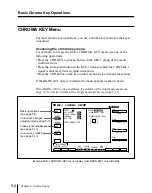
Press any of F4 to F8 to select the foreground video. In a D2 system,
however, F8 (KEY BUS) does not appear.
F4 (1) to F7 (4): input signal to one of the CRK INPUT connectors (CH
1 to CH 4) on the rear panel of the processor.
F8 (KEY BUS): signal selected on the key bus.
6
In a D1 system, if you selected F8 (KEY BUS), press F9 (FRGD
FORMAT) and select the format of the foreground signal.
422: 4:2:2 digital component signal
444: 4:4:4 digital component signal
Note
When using a key bus 4:4:4 format signal for the foreground, you must
first use a setup menu operation to allow two signals (a 4:2:2 format
signal (“LINK A”) and a 0:2:2 format signal (“LINK B”)) to be
combined and selected together by the cross-point button.
For details of the setup menu operation, see page 14-53.
7
Make the same preparations as for an ordinary key transition.
Select “KEY BUS” for both of the key fill and the key source, to carry
out self-keying.
In a D1 system, if you set F9 (FRGD FORMAT) to “444”, select “KEY
BUS” for the key fill, and select “AUTO SELECT” for the key source.
Selecting the LINK A signal on the key fill bus automatically selects the
LINK B signal on the key source bus.
8
Carry out the transition, to insert the key.
9
For an optimum result carry out the adjustments in the next section
“Adjusting the Chroma Key Image” (next page). If necessary, see also
the sections “Video Signal Adjustment” (page 5-12) and “Chroma Key
Masking” (see page 5-13).
Summary of Contents for DVS-7250
Page 10: ......
Page 30: ......
Page 66: ......
Page 67: ...Menu Organization 3 2 Basic Menu Operations 3 6 Chapter 3 Basic Menu Operations ...
Page 274: ......
Page 328: ......
Page 364: ......
Page 488: ......
Page 495: ...Appendixes A 3 Enhanced Wipes 21 23 24 26 27 29 49 300 301 302 303 304 POLYGON ...
Page 534: ......
Page 542: ...Sony Corporation B P Company BZS 7061A WW A AE0 600 01 1 1999 ...


