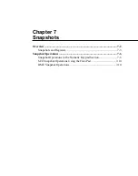
Chapter 7
Snapshots
7-3
Snapshots and Registers
Snapshots are held in units of memory termed registers, numbered from 01 to
99. As shown below, each register comprises seven sub-registers, each
holding the data relating to a different section of the control panel settings.
Basically it is possible to save and recall a whole register (i.e. all sub-
registers) or various sub-registers of a single register.
The DME has 99 registers numbered from 01 to 99 for each channel. They
can be used individually for saving and recalling operations. For more
details, see page 7-13.
Arrangement of snapshot registers
Significance of sub-registers
The settings held in each sub-register of a snapshot are as follows.
M/E-1, M/E-2: Settings on the corresponding M/E bank. This includes the
color background settings and chroma key settings.
PGM/PST: Settings on the PGM/PST bank. This includes the color
background settings.
Frame Mem 1 and 2: Settings for frame memories 1 and 2.
AUX Buses: Settings in the auxiliary bus bank and destination settings for a
routing switcher to be controlled via the BKDS-7700.
CCR: Settings for the color correction functions.
Registers 1 to 99
Sub-
registers
“USER”
group
M/E-1
Frame Mem 1
M/E-2
PGM/PST
Frame Mem 2
AUX Buses
CCR
For channel 1
For channel 2
For channel 4
DME registers
Switcher registers
Registers
01 to 99
Summary of Contents for DVS-7250
Page 10: ......
Page 30: ......
Page 66: ......
Page 67: ...Menu Organization 3 2 Basic Menu Operations 3 6 Chapter 3 Basic Menu Operations ...
Page 274: ......
Page 328: ......
Page 364: ......
Page 488: ......
Page 495: ...Appendixes A 3 Enhanced Wipes 21 23 24 26 27 29 49 300 301 302 303 304 POLYGON ...
Page 534: ......
Page 542: ...Sony Corporation B P Company BZS 7061A WW A AE0 600 01 1 1999 ...


