14-10
Chapter 14
Setup
Setup Relating to the Overall Switcher System (SYSTEM Menu)
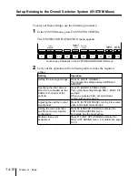
To carry out these settings, use the following procedure.
1
In the SYSTEM menu, press F4 (SYSTEM CONFIG).
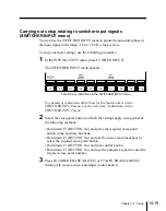
The SYSTEM CONFIGURATION menu appears.
F1
F2
F3
F4
F5
F6
F7
F8
F9
F10
SYSTEM
PHASE
M/E-1
INPUT
WINDOW
REMOTE
PANEL
PGM
WIDE
MLT XPT
ASSIGN
FM&CCR
CONFIG
Function key indications in the SYSTEM CONFIGURATION menu
2
Carry out the operation in the following table to make the required
setting.
Setting the color correction
and frame memory function
configuration
Setting
Operation
Setting the input signal range
Press F2 (INPUT WINDOW).
This toggles the setting between WIDE and
NARROW.
Adjusting the switcher output
signal phase
Press F6 (SYSTEM PHASE), turning it to reverse
video, and adjust control knob 4.
Press F9 (FM&CCR CONFIG) to display the
CCR CONFIGURATION menu.
For details, see the next section.
Specifying the final bank or
block to be controlled via the
PANEL 2 connector of the
switcher
Press F5 (REMOTE PANEL PGM).
This cycles the setting through M/E-1, M/E-2, P/P
and AUX.
When you selected AUX, set an AUX bus
number with control knob 3.
Multiple cross-point
assignment
Press F10 (MLT XPT ASSIGN) to display the
MULTI XPT ASSIGN menu. For details see page
14-12.
Summary of Contents for DVS-7250
Page 10: ......
Page 30: ......
Page 66: ......
Page 67: ...Menu Organization 3 2 Basic Menu Operations 3 6 Chapter 3 Basic Menu Operations ...
Page 274: ......
Page 328: ......
Page 364: ......
Page 488: ......
Page 495: ...Appendixes A 3 Enhanced Wipes 21 23 24 26 27 29 49 300 301 302 303 304 POLYGON ...
Page 534: ......
Page 542: ...Sony Corporation B P Company BZS 7061A WW A AE0 600 01 1 1999 ...

