background image

DVW-522/522P

DIGITAL VIDEOCASSETTE PLAYER

CONTROL PANEL EXTENSION KIT

BKDW-510

CONTROL PANEL CASE

BKDW-511

MAINTENANCE MANUAL

 Part 1

1st Edition (Revised 1)
Serial No. 10001 and Higher (DVW-522)
Serial No. 10001 and Higher (DVW-522P)

Summary of Contents for DVW-522

Page 1: ... DIGITAL VIDEOCASSETTE PLAYER CONTROL PANEL EXTENSION KIT BKDW 510 CONTROL PANEL CASE BKDW 511 MAINTENANCE MANUAL Part 1 1st Edition Revised 1 Serial No 10001 and Higher DVW 522 Serial No 10001 and Higher DVW 522P ...

Page 2: ... Um die Gefahr eines elektrischen Schlages Feuergefahr und Verletzungen zu vermeiden sind bei Wartungsarbeiten strikt die Angaben in der Anleitung zu befolgen Andere als die angegeben Wartungsarbeiten dürfen nur von Personen ausgeführt werden die eine spezielle Befähigung dazu besitzen AVERTISSEMENT Ce manual est destiné uniquement aux personnes compétentes en charge de l entretien Afin de réduire...

Page 3: ...1 2 Details of the Setup Menu 1 23 1 11 3 Setting Check Sheet 1 28 2 Service Overview 2 1 Notes on Power Supply Block 2 1 2 1 1 Warning on Primary Circuit and Electric Shock 2 1 2 1 2 Notes on Resetting the Circuit Breaker 2 1 2 2 Removal Installation of Cabinet 2 1 2 2 1 Cabinet Removal Installation 2 1 2 2 2 Removal Installation of Plate MD 2 3 2 2 3 Connector Panel Removal Installation 2 4 2 2 ...

Page 4: ...n for Cleaning 4 6 4 2 2 Rotary Heads Cleaning 4 7 4 2 3 Upper Drum s Tape Running Surface Cleaning 4 8 4 2 4 Lower Drum s Tape Running Surface and Lead Surface Cleaning 4 9 4 2 5 Stationary Heads Cleaning 4 10 4 2 6 Tape Running System and Tape Cleaner Cleaning 4 11 4 2 7 Fan Motor Cleaning 4 12 4 2 8 Cassette Compartment Cleaning 4 13 5 Maintenance Mode 5 1 Outline 5 1 5 1 1 Operation to the Mai...

Page 5: ...3 PB Clock Phase Setting 6 5 6 3 Adjustment after APR 1 Board Replacement 6 6 6 3 1 CUE Monitor Output Level Adjustment 6 6 6 4 Adjustment after EQ 45 Board Replacement 6 7 6 4 1 ADV Envelope Level Adjustment 6 7 6 4 2 PLL Adjustment 6 8 6 5 Adjustment after CUE 1 Board Replacement 6 9 6 5 1 CUE PB Frequency Response Adjustment 6 9 6 5 2 CUE PB Level Adjustment 6 10 6 6 Adjustment after SS 52 Boar...

Page 6: ......

Page 7: ... boards Section 3 Error Messages Explains the error messages Section 4 Periodic Maintenance and Inspection Explains the cleaning procedure and periodic check As for the replacement procedure of the periodic maintenance parts refer to the Maintenance Manual Part 2 Section 5 Maintenance Mode Explains the maintenance mode CHECK mode As for the ADJUST mode refer to the Maintenance Manual Part 2 Sectio...

Page 8: ... This manual is necessary for application and operation of this unit Maintenance Manual Part 2 Not supplied with this unit This manual describes the information items adjustments board layouts schematic diagrams datailed parts list etc that premise the service based on parts If this manual is required please contact to Sony s service organization ...

Page 9: ...ces Areas where is subjected to electricity noise Areas where is subjected to static electricity noise Horizontal condition Do not slant the front and rear of the unit more than 30 n Fix the unit securely if it is operated at a slant 1 2 Power Supply 1 2 1 Voltage and Power Requirements This unit s power line has a switching regulator and is designed for 90 V through 265 V Power voltage 90 265 V A...

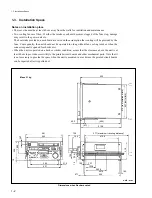
Page 10: ...equently the unit should not be operated too long without fan cooling such as when the connector panel is opened for checks etc When the unit is operated on a desk or similar condition assure that the clearance above the unit is at least 40 cm to provide accessivility to the printed circuit boards and other mechanical parts Note that it is not necessary to provide the space when the unit is mounte...

Page 11: ...42 01 s HOLDER B PLUG for DVW 522 1pc 3 613 640 01 o HOLDER C PLUG for DVW 522P 1pc 3 181 533 01 o CUSHION LOWER 1pc 3 181 534 02 o CUSHION UPPER 1pc 3 181 535 01 o SPACER A 1pc 3 181 536 01 o SPACER B 1pc 3 687 335 01 o INDIVIDUAL CARTON for DVW 522 1pc 3 687 336 01 o INDIVIDUAL CARTON for DVW 522P 1pc 3 701 616 01 o BAG POLYETHYLENE 1pc 3 701 619 01 o BAG POLYETHYLENE STANDARD 1pc 3 701 634 00 o...

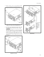
Page 12: ... cables on the connector panel considering that the unit is pulled out 1 Remove the five screws on right and left side panels 2 Install the inner members of the slide rails to the right and left side panels with the screws removed 1 5 Rack Mounting B4x6 Inner member B4x6 Inner member Installation of Inner Member 3 Remove the four feet on the bottom plate If the unit is mounted in the rack with the...

Page 13: ...les c Never use screws PSW4x16 to install the right and left side panels without L angles Be sure to install the panels with the screws B4x6 removed in step 5 Screws for L angles are longer than screws for only panels PSW4x16 without L angles may cause trouble in the unit Installation of L angles B4x6 B4x6 PSW4x16 L angle PSW4x16 L angle PSW4x16 465 427 More than 7 mm Spacer Rack Mounting Front vi...

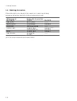
Page 14: ...tors When external cables are connected to the connector on a connector panel during maintenance the hardware listed below or the equivalents must be used Matching Cable Connector Cable Connector BNC 75 Z MALE XLR 3P FEMALE JM 60 stereo phone plug D SUB 15P MALE JUNCTION SHELL 15P D SUB 25P MALE RFU ADAPTOR AV CABLE NOTE 1 This connector is supplied with optional accessory BKDW 510 1 6 Matching Co...

Page 15: ...ng 1 for character superimpose 1 0 Vp p 75 Z sync negative MONITOR OUTPUT R L XLR 3 pinx2 4 dBm 600 Z load low impedance balanced CONTROL PANEL D SUB 15 pin connector RS232C D SUB 25 pin connector HEADPHONES JM 60 stereo phone jack Upper Control Panel up to 12 dBu 8 Z load unbalanced Rear Panel VIDEO OUTPUT 1 2 SUPER RF ADAPTOR AC IN BREAKER MONITOR OUTPUT R L RS232C CONTROL PANEL COMPOSITE VIDEO ...

Page 16: ...GND RS232C 25 pin female external view RS232C Pin No 1 2 3 4 5 6 7 8 9 10 11 12 13 14 15 16 17 18 19 20 21 22 23 24 25 Signal FG Frame Ground TXD Transmitted Data Output RXD Received Data Input RTS Request to Send Output CTS Clear to Send Input DSR Data Set Ready Input SG Signal Ground DCD Data Carrier Detect Input NC NC NC NC NC NC NC NC NC NC NC DTR Data Terminal Ready Output NC NC NC NC NC 1 7 ...

Page 17: ...tch Shorting Land Settings on the Boards c Never change the settings of the factory use switches APR 1 board APR 1 board on board shorting lands and resistor selection Board suffix No 16 and higher Selecting output level Audio Channel MONITOR L CH MONITOR R CH Ref No S1552 1 S1552 2 S1552 3 S1552 4 S1555 1 S1555 2 S1555 3 S1555 4 Fine Adjustment Address No RV901 F 5 RV902 D 5 1 8 Switch Shorting L...

Page 18: ...OFF Ref No S1550 1 S1550 2 S1553 1 S1553 2 Fine Adjustment Address No RV901 F 5 RV902 D 5 Ref No S1551 1 S1551 2 S1554 1 S1554 2 1 Factory Setting 2 When the level variable is selected the level is adjusted with the PHONES level control Selecting output headroom 3 Factory Setting 1 8 Switch Shorting Land Settings on the Boards Output Headroom dB 16 18 20 3 OFF ON OFF ON OFF OFF OFF ON OFF ON OFF O...

Page 19: ... OPEN SHORT OPEN OPEN OPEN OPEN SHORT MOUNT NO MOUNT NO MOUNT NO MOUNT 1 8 Switch Shorting Land Settings on the Boards c Never change the settings of the factory use switches APR 1 board APR 1 board on board shorting lands and resistor selection Board suffix No 41 Selecting output level Audio Channel MONITOR L CH MONITOR R CH Ref No SL902 SL903 SL904 R1038 SL905 SL906 SL907 R1039 Fine Adjustment A...

Page 20: ...NO MOUNT MOUNT Ref No SL908 SL909 SL910 SL911 Fine Adjustment Address No RV901 F 5 RV902 E 5 Ref No SL900 R939 SL901 R940 1 Factory Setting 2 When the level variable is selected the level is adjusted with the PHONES level control Selecting output headroom 3 Factory Setting 1 8 Switch Shorting Land Settings on the Boards Output Headroom dB 16 18 20 3 OPEN SHORT OPEN SHORT OPEN OPEN OPEN SHORT OPEN ...

Page 21: ...ncy response head vibration Refer to the Maintenance Manual Part 2 Vol 1 These switches are used in audio head dumping adjustment If the switch settings are changed when this adjustment is not performed audio frequency response may be failed Factory Setting When the unit is shipped these switches are set to the position based on the adjustment condition CUE 1 board on board switch 1 8 Switch Short...

Page 22: ...r to put the unit into customize menu mode OFF OPEN Customize menu mode disabled ON CLOSE Customize menu mode enabled Factory use Select whether to put the unit into maintenance mode with only front panel operation OFF OPEN Operation disabled ON CLOSE Operation enabled OFF OPEN Enables the write of data in BANK3 ON CLOSE Disables the write of data in BANK3 The message below is displayed on the mon...

Page 23: ...switches for maintenance mode Undefined Undefined Undefined Undefined Pressing this switch enables the changing of the reel position without installing the cassette compartment in the unit Select whether to enable TRACKING VR operation or not OFF OPEN Tracking VR operation enabled ON CLOSE Tracking VR operation disabled Factory use When this switch is pressed de distortion removal of residual dist...

Page 24: ...he SHUTTLE button the VTR is switched to shuttle mode Press the JOG button the VTR is switched to jog mode Prohibiting search dial pressing from switching the mode 1 Turn off the POWER 2 Fix a lower control panel at 90 degrees Refer to Section 2 6 3 Loosen a screw on the backside of the search dial as shown in the figure 4 Slide the mode selection plate in the direction indicated by the arrow unti...

Page 25: ...e arrow until it touches the B portion 8 Check that the shaft of the search dial is seen in the round hole of the mode selection plate and then tighten the screw Back view Mode selection plate B3x14 Round hole The State that the Mode Cannot Be Switched The shaft is not seen in the round hole 1 9 Search Dial Mode Switching Back view B3x14 B portion Mode selection plate The shaft is seen in the roun...

Page 26: ... To use the lower control panel of the DVW series as a desk type remote control unit control panel case BKDW 511 is required Components BKDW 510 Blank panel Remote cable with 15 pin connector BKDW 511 Control panel case Cord stopper Harness clamper 1 10 Installation of BKDW 510 511 56 5 14 5 207 Max 218 22 5 448 441 5 Max Unit mm Dimensions of Control Panel Case ...

Page 27: ...control unit 1 Pass the connector at the end of the remote cable with a 15 pin connector through the control panel case and tighten the screw of the cord stopper to fix 2 Wind the harness clamper round a cable and fix the cable so that it does not move Fixing of Remote Cable 3 Loosen the two knob screws at the bottom of the control panel case by one or two turns Turning of Knob Screws 1 10 Install...

Page 28: ...ighten the two screws of the metal plating shell and connect the remote cable to the connector CONTROL PANEL on the connector panel Connection of Remote Cable Setting After Installation This unit is set to the EXT operation using the CONTROL PANEL switch on the system setup panel 1 10 Installation of BKDW 510 511 Lower control panel Cushion block Control panel case Control panel case Remote cable ...

Page 29: ...1 11 Setup Menu The memory area of the INITIAL SETUP MENU of this unit comprises of three banks Each bank contains identical ITEMs which can be independently set For this reason the VTR operation setups can be changed with the switchover of the banks Some ITEMs have the several SUB ITEMs Each SUB ITEM has DATA as shown below Name of Each Panels 1 11 Setup Menu ...

Page 30: ...e JOG lamp lights accordingly When the search dial is in the JOG mode unclicked position the ITEM SUB ITEM and DATA can be modified 9 9 9 9 9 VAR Button Lower control panel To jump to the top item of the next or preceding category turn the search dial while pressing this button JOG Button Lower control panel Press the JOG button once so that the search dial enters the JOG mode and the JOG lamp lig...

Page 31: ...AR REVERSE FORWARD PHONES CUE L R CH 4 CH 3 CH 2 CH 1 AUDIO MONITOR SELECT DIGITAL LTC VITC CHANNEL CONDITION MENU 3 2 1 EJECT POWER ON OFF Upper Lower Control Panel System Set up Panel SS 52 Board 2 Time counter display 3 MENU button 4 SET button SETUP SELECT switch 1 MENU lamps 1 2 3 RESET button SHUTTLE button 0 JOG button 9 VAR button 8 Search dial 5 STOP button 6 TC button 7 PLAY button Switc...

Page 32: ...EADING COUNTER H12 DRUM RUNNING HOURS resettable H13 TAPE RUNNING HOURS resettable H14 THREADING COUNTER resettable ITEM 000 SERIES OPERATIONAL PARAMETER 002 CHARACTER H POSITION 003 CHARACTER V POSITION 005 DISPLAY INFORMATION SELECT 007 TAPE TIMER DISPLAY 009 CHARACTER TYPE 011 CHARACTER V SIZE 012 CONDITION DISPLAY ON VIDEO MONITOR ITEM 100 SERIES OPERATIONAL PANEL PARAMETER 101 SELECTION FOR S...

Page 33: ... However it is displayed in 1 hour units on the monitor screen without pressing the JOG SHUTTLE button The accumulated tape running hours in the PLAY and SEARCH modes except STILL mode are displayed on the timer counter in 10 hour units NOTE The accumulated tape running hours are displayed in 1 hour units on the timer counter while the JOG SHUTTLE button on the lower control panel is pressed Howev...

Page 34: ...imal number the bottom end 6A for NTSC 81 for PAL Select the information to be displayed by characters that are superimposed on the output signal of the VIDEO OUTPUT 2 and RF ADAPTOR VIDEO connectors when the system setup panel CHARACTER switch is ON 0 Time counter display information and VTR status 1 Time counter display information and user s bits 2 Time counter display information and CTL 3 Tim...

Page 35: ...ed in the VIDEO OUTPUT 2 and RF ADAPTOR VIDEO connectors 01 Standard size 02 Twice the standard size 03 Three times the standard size 04 Four times the standard size Select whether or not to additionally display the channel condition to the superimposing video characters 0 Does not display the condition 1 Displays the condition How the Displayed the Channel Condition The condition is displayed bel...

Page 36: ... 5 steps REMOVE throu MASTER 0 0 10 0 0 5 steps Description This item sets the amount of the video setup that is added to the composite output signal When the MASTER is selected to the ITEM OUTPUT LEVEL the amount of setup in the range from 0 0 to 10 0 is selected by the ITEM MASTER LEVEL that is added to the composite output signal These SUB ITEMs are displayd on the screen but cannot be selected...

Page 37: ... c The items below are used exclusively for adjustment After adjustment is completed the menu data should be returned to the factory setting ITEM No F13 TITLE TRACKING CONTROL VIA SEARCH DIAL DATA No 0 1 Description Select whether the tracking control operation with search dial is enabled or not during DT head playback This item is prepared exclusively for DT adjustment and tracking adjustments Af...

Page 38: ...4 for NTSC 12 for PAL 56 for NTSC 6A for PAL 0 0 0 01 0 ITEM 002 CHARACTER H POSITION 003 CHARACTER V POSITION 005 DISPLAY INFORMATION SELECT 007 TAPE TIMER DISPLAY 009 CHARACTER TYPE 011 CHARACTER V SIZE 012 CONDITION DISPLAY ON VIDEO MONITOR Bank 2 1 11 Setup Menu ITEM 101 SELECTION FOR SEARCH DIAL ENABLE 116 JOG DIAL RESPONSE Bank 1 Bank 3 ITEM 100 SERIES OPERATIONAL PANEL PARAMETER ITEM 700 SE...

Page 39: ... Switch Shorting Land Output Level Output Headroom MONITOR Output Level S100 1 SETUP MENU MODE S100 2 Factory use S100 3 Factory use S100 4 Factory use S100 5 CUSTOMIZE MENU MODE ENABLE S100 6 Factory use S100 7 MAINTENANCE MODE ACCESS ENABLE S100 8 Factory use S701 1 TRCON VR DISABLE S701 2 to 8 Factory use MONITOR L CH MONITOR R CH MONITOR L CH MONITOR R CH MONITOR L CH MONITOR R CH Setting 1 11...

Page 40: ......

Page 41: ...h the screws as shown in the figure B Screw BVTT3x6 Section 2 Service Overview 2 1 Notes on Power Supply Block 2 1 1 Warning on Primary Circuit and Electric Shock The power supply block consists of the AC 139 board and primary peripheral components The whole AC 139 board is on the primary side circuit so pay careful attention to the electric shock Since the inside of a switching regulator is also ...

Page 42: ...op and bottom of the lower control panel assembly then remove the panel B4x6 Bottom Plate Put the unit on its right side down remove six screws and remove the bottom plate B4x6 B4x6 BVTT3x6 B4x6 BVTT3x6 BVTT3x6 B4x6 Right Side Panel 1 Remove four screws and remove the handle 2 Remove four screws and remove the right side panel Upper Lid Loosen three fixing screws and remove the upper lid by moving...

Page 43: ...he direction indicated by the arrows outside then fix Fixing of the Plate MD 6 Install the upper lid 2 2 2 Removal Installation of Plate MD Removal 1 Remove the upper lid Refer to Section 2 2 1 2 Slide the knobs of the plate MD each in the direction indicated by the arrows inside Sliding of the Knob Positions 3 Remove the plate MD Knob Knob Plate MD Plate MD Knob Knob Plate MD Harness 2 2 Removal ...

Page 44: ...ctor Panel 4 Install the connector panel in the reverse order of steps 1 through 3 Connector panel Connector panel Screw BVTT3x6 Screws BVTT3x6 Screws BVTT3x6 2 2 4 Power Supply Panel Removal Installation 1 Turn off the POWER 2 Remove two screws and open the power supply panel Removal of the Power Supply Panel 3 Remove a screw and a spring washer which secure the ground terminal then disconnect co...

Page 45: ...ld 8 Remove the cassette compartment by sliding up it raising up the rear part with the B portion held as shown in the figure n In this time do not move the cassette compartment to right and left and do not widen the right and left side panels If the right and left side panels are widened a gear position might be changed or some parts might be removed Removal of the Cassette Compartment 9 When put...

Page 46: ...ssing the C portions two portions as shown in the figure 13 After confirming that the cassette compartment is fixed to the chassis install the cassette compartment bracket assembly n When looked down on from the top check that the two leaf springs are pressed by the two projections on the cassette compartment 14 Connect the connector CN930 on the CL 29 board Installation of the Cassette Compartmen...

Page 47: ...1 9 CCM 15 CL 29 CP 279 CP 280 CP 282 CUE 1 2 DP 176 DPR 36 DR 200 DT 34 EQ 45 1 FP 58 7 HN 181 6 HN 184 HN 185 5 KY 231 MB 441 PC 70 PD 35 PTC 54 PTC 59 PTC 69 PTC 71 RM 82 SE 228 SS 52 8 SW REG 4 SWC 17 SWC 19 TR 78 TR 79 VPR 1 VR 152 VR 207 2 4 1 Printed Circuit Board Locations Top view ...

Page 48: ...E 1 2 DP 176 DPR 36 DR 200 DT 34 EQ 45 1 FP 58 7 HN 181 6 HN 184 HN 185 5 KY 231 MB 441 PC 70 PD 35 PTC 54 PTC 59 PTC 69 PTC 71 RM 82 SE 228 SS 52 8 SW REG 4 SWC 17 SWC 19 TR 78 TR 79 VPR 1 VR 152 VR 207 2 4 1 Printed Circuit Board Locations Rear Front Bottom view ...

Page 49: ...2 9 2 4 1 Printed Circuit Board Locations Rear view Front view ...

Page 50: ...2 10 Top view of casssette compartment 2 4 1 Printed Circuit Board Locations Top view ...

Page 51: ...tension regulator arm TG 0 tape guide Capstan shaft Cleaning roller block Pinch press block TG 4 tape guide Threading gear block 1 Audio TC head 2 TG 3 tape guide 3 Head drum 4 Threading ring 5 T tension regulator arm 6 CTL head 7 TG 2 tape guide 8 Audio TC head cleaner 9 T drawer arm TG 10 tape guide Pinch roller T reel table T brake assembly INDEX Top view ...

Page 52: ...2 12 2 4 3 Function and Location of Sensors Top view 2 4 3 Function and Location of Sensors Top view of cassette compartment LOWER UPPER ...

Page 53: ...hat is being inserted into the unit 8 Analog digital tape sensor Using a tub on the back side of the cassette tape this sensor detects whether an analog tape or digital tape is being inserted into the unit 9 T reel table rotation sensor This sensor detects the rotation of the take up reel table The FG output signal of this sensor is input to the servo circuit to control the rotation speed of the r...

Page 54: ...wer Blinks switch is set to ON Lights for scores ms at intervals 1 to 2 seconds For the blinking pattern when abnormality occurred refer to the figure shown next page D800 DRUM Amber Blinks during drum microcomputer normal operation Usually lights Blinks for 30 msecond at intervals of about one second The blinking interval is inverted when the drum is locked D2109 DT Amber Blinks during DT microco...

Page 55: ...5 sec 0 5 sec Repeat ROM Checksum error RAM error lighting off System Control Dual Port RAM error scores msec 0 1 sec 0 5 sec 0 5 sec 0 5 sec Repeat DT Dual Port RAM error lighting off scores msec 0 1 sec 0 5 sec 0 5 sec 0 5 sec 0 5 sec Repeat 2 5 LED Indicator Infomation on Boards Blinking Pattern of D711 on SS 52 Board ...

Page 56: ...e moves maximum 90 degrees n The lower control panel can be tilted up to 90 degrees by approximately 15 degree step When using the lower control panel on the tilt turn the knobs clockwise to hold the panel firmly Pulling out Pushing in the Lower Control Panel n Put back the panel assembly in the unit surely after using the unit Knob Lower control panel ...

Page 57: ...w from the arms Installation 6 Fix the arms at the normal position 7 While pushing the black screws and set the notches of the panel assembly to the claws of the arms Then leave from the black screws 8 Fix the lower control panel assembly at 90 degrees Then fix the panel assembly with the two screws 9 Connect the harness of the panel assembly to the connector CN580 on the system set up panel Insta...

Page 58: ... panel and wind the tape inside the cassette n Do not shift the ME lever during normal operation during reel table operation Repeat steps 4 and 5 until the unit is put into the unthreading end state and until the tape is wound completely Winding of a Tape 6 Fix the lower control panel assembly at the position of 90 degrees Refer to Section 2 6 7 Turn the yellow pulley of the cassette compartment m...

Page 59: ...01 c Do not use a cotton swab to clean the rotary heads 2 9 Cleaning When the Heads are Clogged 2 9 Cleaning when the Heads are Clogged If the video heads are clogged clean the heads as the following procedure If the video heads are clogged after cleaning by cleaning tape clean them by cleaning piece 2 9 1 Cleaning by Cleaning Tape n Make sure to use the cleaning tape BCT 5CLN or BCT D12CL If the ...

Page 60: ...ng cloth slightly against the rotary heads 7 Rotate the inner drum slowly counterclockwise two or three turns and clean the rotary heads with the cleaning cloth held c Be sure to rotate the inner drum counterclockwise and clean the rotary heads along the circumference Do not rotate the inner drum in the direction opposite to the specified direction clockwise or clean it in the vertical direction T...

Page 61: ...J 6269 800 A Extension Board L EX 365 Large sized printed circuit board for check and adjustment 2 J 6269 810 A Extension Board S EX 377 Small sized printed circuit board for check and adjustment 3 3 184 527 01 Cleaning Cloth 15 cm x 15 cm Cleaning 4 8 960 073 01 Alignment Tape ZR5 1 Digital Video and Audio alignments for NTSC 8 960 073 11 Alignment Tape ZR2 1 Tracking alignments for digital for N...

Page 62: ... in preparing the cables 1 In case of the direct connection with PC 1 2 3 4 5 6 7 8 9 10 11 12 13 14 15 16 17 18 19 20 21 22 23 24 25 FG TXD RXD RTS CTS DSR SG DCD NC NC NC NC NC NC NC NC NC NC NC DTR NC NC NC NC NC 1 2 3 3 2 4 7 5 8 6 6 7 5 8 1 9 10 11 12 13 14 15 16 17 18 19 20 4 21 22 23 24 25 FG TXD RXD RTS CTS DSR SG DCD NC NC NC NC NC NC NC NC NC NC NC DTR NC NC NC NC NC Signal 25PIN 9PIN DB...

Page 63: ...C NC DTR NC NC NC NC NC Terminal Server DVW RJ12 Modular type DB25 3 In case of the connection with PC via MODEM MODEM DVW DB25 DB25 1 2 3 4 5 6 7 8 9 10 11 12 13 14 15 16 17 18 19 20 21 22 23 24 25 2 11 ISR RTS TXD SG NC RXD CTS 1 2 3 4 5 6 FG TXD RXD RTS CTS DSR SG DCD NC NC NC NC NC NC NC NC NC NC NC DTR NC NC NC NC NC FG TXD RXD RTS CTS DSR SG DCD NC NC NC NC NC NC NC NC NC NC NC DTR NC NC NC ...

Page 64: ......

Page 65: ...ue Detected when the FG frequency at a supply or take up reel is zero 0 or when the tension detected from a tension sensor is less than 15 g Depends on the comparison between the tape speed using the FG frequency at supply and take up reels and the designated speed Detected using the FG frequency or current at supply and or take up reels Detected when the tension detected from a tension sensor is ...

Page 66: ... of SWC 19 board DPR DPR 36 board VPR IC753 of VPR 1 board The interface between the following CPU on SS 52 board and main CPU of IC5 on SS 52 board is defective when the POWER switch is turned ON DT IC2104 main servo SV1 IC750 drum servo SV2 IC700 The operational defect of main CPU of IC5 on SS 52 board is defective when the POWER switch is turned ON Not display on the video monitor Detection Det...

Page 67: ...djustment data on the DR 200 board is detected The operational defect of the NV RAM IC6 RF adjustment data on the SWC 19 board is detected Then reset the data in the NV RAM to the condition at exfactory Error message NV RAM TROUBLE sub error message menu 1 menu 2 menu 3 id code SWC 1 SWC 2 SWC 3 SWC 4 SV NV RAM TROUBLE NV RAM TROUBLE sub error message RF ADJUST DATA LOST Detection Detected by the ...

Page 68: ......

Page 69: ... display the actual number Example In a case of the total hours that the power of the unit has been turned on is 12 345 hours Time Counter Display Monitor Display Section 4 Periodic Maintenance and Inspection SET UP MENU H01 OPERATION HOURS H02 DRUM RUNNING HOURS H03 TAPE RUNNING HOURS H04 THREADING COUNTER MONITOR DISPLAY Display the time by an hour Display the time by an hour Display the time by...

Page 70: ... guarantee term of parts Use this table as guidelines for maintenance and inspection The replacement time of parts varies depending on the operating environment and conditions of the unit n The part marked with in the table is replaced simultaneously with when the part in the column below its mark is replaced Item Drum Block Inner Drum Assembly Brush Slip Ring Assembly Drum Assembly Cleaners Clean...

Page 71: ... use the unit in an air conditioned place at middle tempareture and humidity of the specifications and lesser dust circumstances In addition the tapes should be kept in the same conditions To maintain the steady performance these are recommended to clean the tape running system and autmatic adjustment of RF system every the following hours as a guide every 50 hours H02 Cleaning by cleaning tape Re...

Page 72: ...ame PLUNGER SOLENOID REGULATOR ASSY TENSION T TEN ASSY DRAWER ASSY T BOX ASSY GEAR RING ASSY THREADING ROLLER RING ROLLER RING B GUARD PINCH ARM RAIL CL GUIDE CASSETTE COMPARTMENT ASSY Part No 1 454 417 41 A 8267 795 C A 8267 423 B A 8267 381 E A 8267 424 A A 8267 395 E 3 180 677 01 3 180 679 01 3 180 853 01 3 180 874 02 A 8267 863 B Q ty 2 1 1 1 1 1 2 1 1 1 1 n Replace the parts shown in the tabl...

Page 73: ...efer to Volume 1 of MAINTENANCE MANUAL Part 2 Refer to Section 2 3 2 Refer to Section 2 3 11 Refer to Section 2 3 12 Refer to Section 2 3 13 Refer to Section 2 3 8 Refer to Section 2 3 10 Refer to Section 2 3 9 Refer to Section 5 1 Exploded views Refer to Section 2 3 4 1 Periodic Check ...

Page 74: ...ach part and to apply an excessive force during cleaning Do not touch the greased portions during cleaning If grease attaches to a cleaning cloth replace the cleaning cloth by new one If a cleaning cloth smeared with grease is used grease may attach to the places where it should not Do not insert a cassette tape before a cleaning fluid completely evaporates after cleaning 2 Preparation 1 Turn the ...

Page 75: ...y heads 3 Rotate the inner drum slowly counterclockwise two or three turns and clean the rotary heads with the cleaning cloth held c Be sure to rotate the inner drum counterclockwise and clean the rotary heads along the circumference Do not rotate the inner drum in the direction opposite to the specified direction clockwise or clean it in the vertical direction This may damage the rotary heads and...

Page 76: ...01 Procedures 1 Press the cleaning cloth moistened with a cleaning fluid slightly against the upper drum s tape running surface shaded portion in the figure 2 Clean the upper drum s tape running surface along the circumference two or three times c Pay careful attention when cleaning the edge portion below the upper drum 3 After cleaning wipe it with a dry cleaning cloth two or three times Upper Dr...

Page 77: ...ong the drum lead surface and remove the magnetic powder c 1 Do not use a metallic skewer instead of the skewer This may damage the tape running surface 2 Tracking may be badly influenced when magnetic powder attaches to the drum lead surface Remove the magnetic powder completely during cleaning 2 Clean the drum lead surface and lower drum s tape running surface shaded portion in the figure with a...

Page 78: ...aces of the audio TC head and CTL head in the vertical direction with a cleaning cloth moistened with a cleaning fluid c An error may occur in the playback when magnetic powder attaches to the head gap portion of the audio TC head and CTL head Remove the magnetic powder completely during cleaning 2 After cleaning wipe it with a dry cleaning cloth two or three times Stationary Heads Cleaning 4 2 Cl...

Page 79: ...eaner from top to bottom four or five times At this time do not move the paper from bottom to top w Do not touch the edge portion of the tape cleaner with bare hands 2 Clean the tape running surfaces shaded portions in the figure of each guide with cleaning cloth moistened with a cleaning fluid 3 After cleaning clean it with a dry cleaning cloth two or three times 4 2 Cleaning Tape Running System ...

Page 80: ...ools Cleaning cloth 3 184 527 01 Cleaning fluid 9 919 573 01 Vacuum cleaner Procedures 1 Remove the power panel Refer to Section 2 2 1 2 Remove the connector panel Refer to Section 2 2 3 3 Remove the dust on the fan motors using a vacuum cleaner 4 Clean the fin shaded portion in the figure with cleaning cloth moistened with cleaning fluid 5 Install the connector panel Refer to Section 2 2 3 6 Inst...

Page 81: ...Cloth or Gauze Vacuum cleaner Procedures 1 Remove the cassette compartment from the unit Refer to Section 2 3 2 Remove the dust on the cassette compartment from the cassette insertion inlet using a vacuum cleaner 3 Clean the compartment block shaded portion in the figure with a dry cloth or gauze c Do not apply an excessive force to the compartment block Cassette Compartment Cleaning 4 2 Cleaning ...

Page 82: ......

Page 83: ...e Manual Part 2 C0 SERVO DT CHECK C1 RF CHECK C2 AUDIO VIDEO CHECK C4 OTHERS CHECK A0 SERVO DT ADJUST A1 RF ADJUST A2 AUDIO VIDEO ADJUST The contents of the maintenance mode are superimposed on the video monitor that is connected to the VIDEO OUTPUT COMPOSITE 2 connector or RF ADAPTOR VIDEO connector The figure below shows an example of the screen display Superimposed Screen Mode Screen when Maint...

Page 84: ... can be changed 6 6 6 6 6 JOG button Lower control panel The JOG lamp lights when this button is pressed once The 7 search dial is then set to the JOG mode When the 7 search dial is turned while pressing this button during manual adjustment the adjustment data can be changed 7 7 7 7 7 Search dial Lower control panel The search dial selects each menu in the JOG mode To change the adjustment data du...

Page 85: ...RVO EJECT PLAY STOP RESET SHUTTLE JOG VAR REVERSE FORWARD 1 Time counter 4 CTL button 6 JOG button 5 SHUTTLE button 7 Search dial 3 SET button 2 MENU button Switching power supply Drum S100 SS board S100 7 MAINTENANCE MODE ACCESS ENABLE switch 9 S301 DIAG ADJUST 2 switch ADJ 8 S300 DIAG ADJUST 1 switch ADJ 5 1 Outline ...

Page 86: ...screen is displayed The maintenance mode is then exited Mode Screen Activating the maintenance mode on lower control panel When the S100 7 SS board is set to ON upper position the maintenance mode can be activated by the operation mentioned below 1 Press the 2 MENU button once The mode then changes from operation mode to setup menu mode 2 Press the 3 SET button while pressing the 4 CTL button The ...

Page 87: ...UTTLE button 7 Search dial 3 SET button 2 MENU button Switching power supply Drum S100 SS board S100 7 MAINTENANCE MODE ACCESS ENABLE switch 9 S301 DIAG ADJUST 2 switch ADJ 8 S300 DIAG ADJUST 1 switch ADJ SETUP MENU SET U BIT TC CTL COUNTER STNDBY SERVO EJECT PLAY STOP RESET SHUTTLE JOG VAR REVERSE FORWARD 5 1 Outline ...

Page 88: ...5 2 2 C02 PLUNGER SOL CHECK Refer to section 5 2 3 C03 REEL CAPSTAN MOTOR FG CHECK Refer to section 5 2 4 C050 DT DRIVER CHECK C051 SG LOOP CHECK C05 DIGITAL DT CHECK Refer to section 5 2 5 C1 RF CHECK Refer to section 5 3 C10 CHANNEL CONDITION C2 AUDIO VIDEO CHECK Factory Use 1 C4 OTHERS CHECK Refer to section 5 4 C020 PINCH ROLLER C021 S REEL BRAKE C022 T REEL BRAKE C023 CLEANING ROLLER C40 ROM ...

Page 89: ...STAN FREE SPEED A011 RF SWITCHING POS A012 NV RAM CONTROL A02 DIGITAL DT ADJUST A020 CAPSTAN FG LEVEL A021 DRIVE GAIN A022 HEAD OFFSET LEVEL A023 NV RAM CONTROL A1 RF ADJUST Refer to the Volume 1 of the Maintenance Manual Part 2 A10 A11 A17 ADJUST A11 PLAY PLL A12 ADV EQUALIZER A14 SHUTTLE FWD PLL A15 SHUTTLE REV PLL A16 VAR FWD PLL A17 VAR REV PLL A19 ADV LEVEL A1F NV RAM CONTROL A2 AUDIO VIDEO A...

Page 90: ...ck mode is displayed it is ejected automatically SERVO DT CHECK C00 04 SERVO CHECK C05 DIGITAL DT CHECK SERVO CHECK C00 INPUT CHECK C01 MOTOR CHECK C02 PLUNGER SOL CHECK C03 REEL CAPSTAN MOTOR FG CHECK SERVO CHECK INPUT CHECK C000 CASSETTE SW C001 CASSETEE COMP SW C002 TOP END SENSOR C003 DEW SENSOR C0 C00 04 C00 C00 DIGITAL DT CHECK C050 DT DRIVER CHECK C051 SG LOOP CHECK SERVO CHECK MOTOR CHECK ...

Page 91: ...5 9 Screen during check Refer to section 5 2 4 This check is initiated SERVO CHECK REEL CAPSTAN MOTOR FG CHECK S REEL FG MOTOR CHECK CHECKING C03 C03 SET SET MENU 5 2 Servo DT System Check Mode ...

Page 92: ... page 5 15 SERVO CHECK C00 INPUT CHECK C01 MOTOR CHECK C02 PLUNGER SOL CHECK C03 REEL CAPSTAN MOTOR FG CHECK C000 C0 SERVO DT CHECK C00 04 SERVO CHECK SERVO CHECK INPUT CHECK C000 CASSETTE SW C001 CASSTE COMP SW C002 T REEL BRAKE C003 CLEANING ROLLER SERVO CHECK INPUT CHECK C000 CASSETTE SW 1 REEL HUB 2 METAL OX 3 THICKNESS 4 SPARE 5 SPARE 6 DGTL ANLG 7 N A 8 N A 123 SW 87654321 4 5 00000000 6 C00...

Page 93: ...ed in the specified position or when the display does not return from 1 to 0 Check the corresponding sensors on the PTC 59 board Also check the sensor input circuit on the DR 200 board 1 Reel hub diameter sensor 2 Metal oxide tape sensor 1 3 Tape thickness sensor 4 Spare sensor 2 5 Spare sensor 1 6 Digital analog tape sensor 1 This sensor doesn t function in this unit Cassette tab sensors 1 throug...

Page 94: ... confirm that changes to the corresponding number when they are released In case of NG When is not displayed in the specified position or when the display does not return from to the corresponding number Check the corresponding sensors on the PC 70 board Also check the sensor input circuit on the DR 200 board SERVO CHECK INPUT CHECK C001 CASSETTE COMP SW SW1 CASSETTE IN SW 1 SW2 CASSETTE IN SW 2 S...

Page 95: ... size sensor SW1 Cassette in switch 1 Cassette in sensor L SW2 Cassette in switch 2 Cassette in sensor R Cassette in sensor R Cassette in sensor L Cassette size sensor Front Rear Switch Position in Compartment Block Top View of the Cassette Compartment 5 2 Servo DT System Check Mode ...

Page 96: ... 1 and 2 in the figure below Also confirm that the display changes from ON to OFF when the screwdriver is released from the sensors In case of NG When ON is not displayed in the specified position or when the display does not return from ON to OFF Check only the sensors Also check the sensor input circuit on the DR 200 board SERVO CHECK INPUT CHECK C002 TOP END SENSOR END TOP SENSOR SENSOR OFF OFF...

Page 97: ... sensor with a dry cotton swab to eliminate water Confirm that the display on the monitor screen returns from WET to DRY when a wind is blown against the sensor using a blower to evaporate moisture In case of NG When the display does not change from DRY to WET even if the sensor is moistened Check only the sensor DEW condensation detection sensor on HN 185 board SERVO CHECK INPUT CHECK C003 DEW SE...

Page 98: ... C00 INPUT CHECK C01 MOTOR CHECK C02 PLUNGER SOL CHECK C03 REEL CAPSTAN MOTOR FG CHECK C010 C0 SERVO DT CHECK C00 04 SERVO CHECK SERVO CHECK MOTOR CHECK C010 S REEL MOTOR C011 T REEL MOTOR C012 THREADING MOTOR C013 CASSETTE COMP C014 CAPSTAN MOTOR C015 DRUM MOTOR C016 REEL SHIFT MOTOR SERVO CHECK MOTOR CHECK C010 S REEL MOTOR TURN JOG DIAL IN JOG MODE S301 SS 52 RETURN C011 SERVO CHECK MOTOR CHECK...

Page 99: ...operation of the reel shift motor and the function of the reel position sensor For more details refer to page 5 22 SERVO CHECK MOTOR CHECK C014 CAPSTAN MOTOR S300 SS 52 CHECK S301 SS 52 RETURN SERVO CHECK MOTOR CHECK C015 DRUM MOTOR SPEED PHASE PG S300 SS 52 CHECK S301 SS 52 RETURN SERVO CHECK MOTOR CHECK C016 REEL SHIFT MOTOR S300 SS 52 CHECK S301 SS 52 RETURN C014 C015 C016 SET MENU SET MENU SET...

Page 100: ...00 board b C011 T REEL MOTOR This mode checks the rotation of the T reel motor Turn the T reel motor using a search dial JOG mode Dial Rotation direction of the T reel motor FWD FORWARD 2 REV REVERSE 3 Confirm that the T reel motor rotates in the direction specified by the dial after the T brake solenoid is turned on and after the T reel brake is released In case of NG When the ON operation sound ...

Page 101: ...e Check the threading motor and the FG sensor on the PTC 59 board Also check the threading motor driver circuit DR 200 board and the threading FG amplifier circuit DR 200 board When the display remains with the unit set to the thread end unthread end state Check the thread end sensor and unthread end sensor on the TR 79 board Unthreading end state Threading motor Threading ring Unthread end sensor...

Page 102: ... the display on the monitor screen changes as shown below DOWN VERT HORIZ UP In case of NG When the cassette compartment motor does not rotate Check the cassette compartment motor Also check the cassette compartment motor driver circuit DR 200 board When the compartment block goes up and down normally but the display does not change Check the cassette down sensor Also check the sensor input circui...

Page 103: ...apstan FG amplifier input circuit DR 200 board f C015 DRUM MOTOR This mode checks the rotation of the drum motor 1 Press the SET button or switch S300 on the SS board to initiate this check The display on the monitor screen at that time is as shown below SPEED NG PHASE UNLOCK PG NO EXIST 2 Confirm that the display on the monitor screen changes as shown at right after a little while In case of NG W...

Page 104: ...changes as shown below In case of NG When the reel shift motor does not rotate Check the reel shift motor Also check the reel shift motor driver circuit DR 200 board When the display remains with the reel table moved to the L position or S position Check the L position S position sensor PTC 71 board L position sensor on PTC 71 board S position sensor on PTC 71 board Reel shift motor S position sta...

Page 105: ...ore details refer to page 5 26 SERVO CHECK C00 INPUT CHECK C01 MOTOR CHECK C02 PLUNGER SOL CHECK C03 REEL CAPSTAN MOTOR FG CHECK C020 C0 SERVO DT CHECK C00 04 SERVO CHECK SERVO CHECK PLUNGER SOLENOID CHECK C020 PINCH ROLLER C021 S REEL BRAKE C022 T REEL BRAKE C023 CLEANING ROLLER SERVO CHECK PLUNGER SOLENOID CHECK C020 PINCH ROLLER S300 SS 52 CHECK S301 SS 52 RETURN C021 SERVO CHECK PLUNGER SOLENO...

Page 106: ...returns to the submenu 3 Push the pinch lever slightly in the direction of the pinch solenoid with fingers The core of the pinch solenoid then returns to the former position In case of NG When the sound indicating that the pinch solenoid is turned on is not generated or when the monitor screen does not change Check the pinch solenoid Also check the solenoid driver circuit on the DR 200 board Pinch...

Page 107: ...cuit on the DR 200 board c C022 T REEL BRAKE This mode checks the operation of the T reel brake solenoid 1 Press the SET button or switch S300 on the SS board Confirm by the generation of a sound that the T reel brake solenoid is turned on 2 Press the MENU button or switch S301 on the SS board The core of the T reel brake solenoid then returns to the former position The monitor screen returns to t...

Page 108: ...rns to the submenu Note The cleaning roller solenoid is burned when it continuosly remains on If the cleaning roller solenoid is not released from the drum turn the power of this unit off as soon as possible In case of NG When the cleaning roller dose not touch the drum or it is not release from the drum Check the cleaning roller solenoid Also check the solenoid driver circuit on the DR 200 board ...

Page 109: ... motor check is performed As the check advances the display in the fifth line changes Confirm that all the checks are completed and that the CHECK COMPLETE message is displayed on the monitor screen In case of NG The screen at right is one example When the contents of each trouble are displayed on the monitor screen refer to the next page SERVO CHECK C00 INPUT CHECK C01 MOTOR CHECK C02 PLUNGER SOL...

Page 110: ...ICTION Checks the offset and friction levels of the S reel In case of NG Check the S reel motor C010 S REEL MOTOR If no abnormality is found adjust the offset and friction of the S reel A004 S REEL OFFSET FRIC e T REEL OFFSET FRICTION Checks the offset and friction levels of the T reel In case of NG Check the T reel motor C011 T REEL MOTOR If no abnormality is found adjust the offset and friction ...

Page 111: ...ph drive amplifier For more details refer to page 5 30 C051 SG LOOP CHECK Checks the feedback loop of the strain gauge For more details refer to page 5 31 C050 C0 SERVO DT CHECK C05 DIGITAL DT CHECK DIGITAL DT CHECK C050 DT DRIVER CHECK C051 SG LOOP CHECK DIGITAL DT CHECK C050 DT DRIVER CHECK No operation Start auto check C051 DIGITAL DT CHECK C051 SG LOOP CHECK No operation Start auto check SET M...

Page 112: ...r screen In case of NG The screen at right is one example When the CHECK COMPLETE message is not displayed on the monitor screen Check bimorph drive amplifier DT 34B board and slip ring Also check the bimorph drive control circuit SS board 1 DIAL 2 SET or S300 During check Check completed OK Check completed NG DIGITAL DT CHECK C050 DT DRIVER CHECK No operation Start auto check DIGITAL DT CHECK C05...

Page 113: ... one example When the CHECK COMPLETE message is not displayed on the monitor screen Execute the DT driver check C050 DT DRIVER CHECK If no abnormality is found in this case check the advance head strain gauge of the inner drum or its signal transmission system slip ring etc 1 DIAL 2 SET or S300 During check Check completed OK Check completed NG DIGITAL DT CHECK C051 SG LOOP CHECK No operation Star...

Page 114: ...g playback in units of three stages on the monitor screen For more details refer to next page RF CHECK MODE C10 CHANNEL CONDITION RF CHECK MODE C10 CHANNEL CONDITION Grn Yel Red VIDEO Ach VIDEO Bch VIDEO Cch VIDEO Dch AUDIO Ach AUDIO Bch AUDIO Cch AUDIO Dch C10 MAINTENANCE MODE C0 SERVO DT CHECK C1 RF CHECK C2 AUDIO VIDEO CHECK C4 OTHERS CHECK A0 SERVO DT ADJUST A1 RF ADJUST A2 AUDIO VIDEO ADJUST ...

Page 115: ...s in the positions other than Grn clean the drum rotary head a Cleaning by the cleaning tape Refer to Section 2 9 1 Cleaning time is five seconds b Cleaning by the cleaning cloth Refer to Section 2 9 2 If the channel condition is not improved after performing the step a and b there is a possibility to improve the situation by use of cleaning tape repeatedly It should be less than 4 times of 5 seco...

Page 116: ...e Status Reporting system The ISR system can perform the operation monitoring and self diagnosis check of each broadcast equipment by using the personal computer installed the ISR application software Sony BZI 500 501 C40 OTHERS CHECK MODE C40 ROM VERSION C41 SERIAL NUMBER C42 RS 232C STATUS C45 MEMORY CHECK C46 HOUR METER OTHERS CHECK MODE C40 ROM VERSION DVW 522 SYS1 V1 00 SYS2 V1 00 SV1 V1 00 S...

Page 117: ... For more details refer to page 5 38 The data value in the figure at left is one example C45 SET MENU C46 SET MENU OTHERS CHECK MODE C45 MEMORY CHECK 0000 24 07 00 F0 0004 24 07 00 F0 0008 24 07 00 F0 000C 24 07 00 F0 0010 24 07 00 F0 0014 24 07 00 F0 0018 24 07 00 F0 001C 24 07 00 F0 0020 24 07 00 F0 0024 24 07 00 F0 OTHERS CHECK MODE C46 HOUR METER DRUM HOURS 234 TAPE HOURS 123 THREAD COUNTER 12...

Page 118: ...sion value is one example 1 SYS1 IC12 on SS 52 board 2 SYS2 IC54 on SS 52 board 3 SV1 IC761 on SS 52 board 4 SV2 IC700 microprocessor on SS 52 board 5 DT IC211 on SS 52 board 6 DR IC3 microprocessor on DR 200 board 7 APR IC51 microprocessor on APR 1 board 8 VPR IC753 microprocessor on VPR 1 board 9 FP IC6 microprocessor on FP 58 board KY IC1 microprocessor on KY 231 board SWC IC2 microprocessor on...

Page 119: ...mission T on ATN OPC or QRESP transmission W waiting for ACK X XOFF received waiting for XON 4 Device ID is desplayed a name that sets by DEVID command of ISR protocol Even if the power is turned off this device ID is kept till it changes by DEVID command 5 Displays the number of the parity error PE framing error FE and overrun error OE of receiving data 6 The number with indicates the pin number ...

Page 120: ...h dial JOG mode 2 Turn the search dial in the reverse direction while pressing the JOG or SHUTTLE button The display value then becomes zero 0 To return the display value to the former value after that turn the search dial in the forward direction 3 For other items to be reset repeat steps 1 and 2 4 Press the SET button or switch S300 on the SS board Resetting is then completed This value is one e...

Page 121: ...activate and terminate the maintenance mode refer to Section 5 1 1 6 1 1 Index for Board Replacement Index Board Electrical Alignment Location APR 1 Section 6 3 3 CUE 1 Section 6 5 6 DPR 36 2 EQ 45 Section 6 4 5 SS 52 Section 6 6 4 VPR 1 Section 6 2 1 DPR 36 board does not need the electrical alignment ...

Page 122: ...a screw and remove the board retainer L or S Board retainer L Screws with stopper Board retainer S 2 Pull up the eject levers on the board in the direction of the arrows when pulling out the board from the connector n Do not try to pull the board by grasping any of the components on the board Pull out the board with equal force for both sides 3 Disconnect the connected harness Eject levers ...

Page 123: ...wn the eject levers as shown in the figure 6 Insert the protrusion of the board retainer L or S into the square hole and tighten the screw 6 1 General Information for Boards Replacement Eject levers Protrusion Board retainer L Board retainer S Square hole Square hole Protrusion Screws ...

Page 124: ...e search dial is turned while pressing the JOG button the adjustment data can be changed COMPOSITE 1 2 OUT A 100 1 IRE 714 7 mV p p for NTSC A 700 7 mV p p for PAL A STEP 2 1 Connect the waveform monitor to COMPOSITE 2 OUT connector 2 Play back the 100 color bars portion 00 00 10 00 of the alignment tape ZR5 1 1P ZR5 1 for NTSC ZR5 1P for PAL 3 On the menu of maintenance mode set as follows A2 AUD...

Page 125: ...ve adjustment data 2 On the menu of maintenance mode set as follows A2F NV RAM CONTROL 3 Execute SAVE ALL ADJUST DATA 6 2 3 PB Clock Phase Setting Procedures STEP 1 1 On the menu of maintenance mode set as follows A2 AUDIO VIDEO ADJUST A20 VPR VR 0 2 Setting at PB CK27 DL When the search dial is turned while pressing the JOG button the setting data can be changed Specifications DATA F0 STEP 2 1 Sa...

Page 126: ...nt Tools Measuring equipment Audio analyzer Procedures STEP 1 1 Connect the audio analyzer to MONITOR OUTPUT L R 2 Select CUE at the MONITOR SELECT L R 3 Play back the 1 kHz 0 VU signal portion 00 00 01 25 of the alignment tape ZR5 1 1P ZR5 1 for NTSC ZR5 1P for PAL 4 Adjustments MONITOR L 1RV900 APR 1 D 4 MONITOR R 1RV903 APR 1 E 4 Specifications 4 0 0 1 dBu terminated by 600 Z 6 3 Adjustment aft...

Page 127: ...D EQ CNF AC EQ ADV BD EQ C D E F ADV AC EQ CNF AC PLL VIT BD PLL VIT TP103 TP104 B G F E D C B A 1 2 3 4 A EQ 45A ADV AC EQ CNF BD B C D E F G 1 2 3 4 ADV BD EQ CNF AC EQ CNF BD EQ CNF AC PLL VI ADV BD PLL VI TP423 TP523 STEP 2 1 Connect the oscilloscope to TP104 and TP523 on the EQ 45 2 Play back the alignment tape ZR5 1 1P 3 On the menu of maintenance mode set as follows Ajust at Bch LEVEL When ...

Page 128: ...the Adjust Complete message is displayed on the monitor screen 5 Press the MENU button or switch S301 on the SS board to return to the RF ADJUST MODE menu screen STEP 2 1 Save adjustment data 2 On the menu of maintenance mode set as follows A1F NV RAM CONTROL 3 Execute SAVE ALL ADJUST DATA 2 Insert alignment tape 3 SET or S300 Adjustment completed 4 MENU or S301 6 4 Adjustment after EQ 45 board re...

Page 129: ...ape ZR5 1 1P ZR5 1 for NTSC ZR5 1P for PAL 3 Adjustment 1RV901 CUE 1 A 4 Specifications MONITOR OUTPUT L R FREQUENCY Hz OUTPUT LEVEL dB 1 k 0 REF 3 k 0 0 5 7 k 0 0 5 10 k 0 0 5 12 k 0 2 0 5 90 0 0 7 1 7 n Correct output levels by correction value of the alignment tape When the specifications are not met switch S102 and then perform this adjustment again 6 5 Adjustment after CUE 1 board replacement...

Page 130: ... 1P for PAL 3 Adjustment 1RV114 CUE 1 C 2 _PB LEVEL ADJ Specifications 4 0 0 1 dBu terminated by 600 Z STEP 2 1 Disconnect the shorting clip 2 Play back the 1 kHz 0 VU signal portion 00 00 01 25 of the alignment tape ZR5 1 1P 3 Adjustment 1RV120 CUE 1 A 3 _PB REF ADJ Specifications 4 0 0 1 dBu terminated by 600 Z 6 5 Adjustment after CUE 1 board replacement 1 648 537 MADE IN JAPAN A A 1 2 3 4 5 6 ...

Page 131: ...ectly even if the ADJUST COMPLETE message is displayed after adjustment is completed 5 After adjustment is completed the ADJUST COMPLETE message is displayed on the monitor screen The alignment tape is then ejected automatically 6 Press the MENU button or switch S301 on the SS board two times to return to the SERVO ADJUST menu screen STEP 2 1 Save adjustment data 2 On the menu of maintenance mode ...

Page 132: ...TILL mode to initiate the adjustment 6 After adjustment is completed the ADJUST COMPLETE message is displayed on the monitor screen 7 Press the MENU button or switch S301 on the SS board to return to the DIGITAL DT ADJUST menu screen 2 Insert alignment tape 3 DIAL 4 SET or S300 5 JOG During adjustment Adjustment completed 7 MENU or S301 6 6 Adjustment after SS 52 board replacement DIGITAL DT ADJUS...

Page 133: ... the SS board to return to the DIGITAL DT ADJUST menu screen STEP 3 1 Save adjustment data 2 On the menu of maintenance mode set as follows A023 NV RAM CONTROL 3 Execute SAVE ALL ADJUST DATA 2 Insert alignment tape 3 DIAL 4 SET or S300 5 PLAY During adjustment Adjustment completed 7 MENU or S301 6 6 Adjustment after SS 52 board replacement DIGITAL DT ADJUST A022 HEAD OFFSET LEVEL MODE PLAY No oper...

Page 134: ......

Page 135: ...3 A for PAL A 8275 904 A for NTSC EQ 45 PB RF equalizer A 8275 358 A for PAL A 8275 360 A for NTSC CUE 1 CUE LTC PB circuits A 8275 909 A for PAL A 8275 910 A for NTSC SS 52 System Servo Digital DT control A 8275 913 A for PAL A 8275 902 A for NTSC DT 34 DT driver DR 200 Motors driver Drum Capstan S T reels Threading Reel shift Cassette up down Solenoids driver Pinch S T brake Cleaning CCM 15 Thre...

Page 136: ...7 2 7 2 OVERALL 1 4 OVERALL 1 4 7 2 Overall Signal Processing System OVERALL 1 4 DVW 522 522P ...

Page 137: ...7 3 7 3 OVERALL 2 4 OVERALL 2 4 Signal Processing System OVERALL 2 4 DVW 522 522P ...

Page 138: ...7 4 7 4 OVERALL 3 4 OVERALL 3 4 Control System OVERALL 3 4 SS 52B Board Circuit to Other Boards DVW 522 522P ...

Page 139: ...7 5 7 5 Control System OVERALL 4 4 SS 52B Board Circuit to Other Boards DVW 522 522P OVERALL 4 4 OVERALL 4 4 ...

Page 140: ......

Page 141: ... suitable See Fig A The material contained in this manual consists of information that is the property of Sony Corporation and is intended solely for use by the purchasers of the equipment described in this manual Sony Corporation expressly prohibits the duplication of any portion of this manual or the use thereof for any purpose other than the operation or maintenance of the equipment described i...

Page 142: ...Printed in Japan Sony Corporation 2000 2 08 B P Company 1995 DVW 522 522P UC EK E 3 188 743 02 ...

Reviews: