5-33
5-3. RF System Check Mode
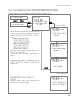
a) C10: CHANNEL CONDITION
This mode can display the error condition in all the video and audio channels
during playback in units of three stages on the monitor screen.
The channel condition indicator on the upper control panel indicates the error
condition in the worst channel among all the video and audio channels.
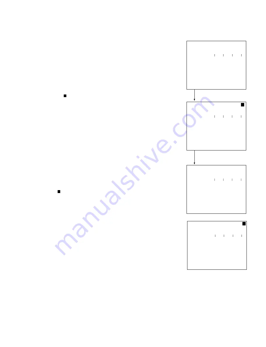
(1) Press the SET button (or switch S300 on the SS board) on the screen at right.
At that time, the unit temporarily exits the maintenance mode. This enables
the normal operation.
(Prompt “
” is displayed in the upper right position of the superimposed
screen, and the time counter is put into the normal state.)
(2) Insert the cassette tape recorded by the digital Betacam and play back it in
PLAY mode. The “>>>” display then appears on the monitor screen.
Confirm that the “>>>” display appears in the Grn position in all the
channels.
(3) To terminate the operation, stop the tape running and eject the cassette tape.
(The “>>>” display disappears.)
Press the MENU button (or switch S301 on the SS board) to return to the
maintenance mode.
(The “
” display disappears on the monitor screen, and the time counter
displays menu number C10.)
When the “>>>” display appears in the positions other than “Grn” , clean the
drum (rotary head).
(a) Cleaning by the cleaning tape (Refer to Section 2-9-1.)
*
Cleaning time is five seconds.
(b) Cleaning by the cleaning cloth (Refer to Section 2-9-2.)
If the channel condition is not improved after performing the step (a) and (b),
there is a possibility to improve the situation by use of cleaning tape repeatedly.
It should be less than 4 times of 5 seconds cleaning in total.
If the channel condition is not improved in the way mentioned above, the
possible causes below are considered.
Playback tape fault: • The tape is damaged.
• The recording state is bad.
Main unit faults:
• Tape running system adjustment defect/part
installation defect
• RF system adjustment defect
• DT system adjustment defect
• Worn head
• Harness defect
• Brush/slip ring defect
• Circuit defect
(1)
[SET]
or
[S300]
(2) Playback
(
3)
[EJECT]
[MENU]
or
[S301]
RF CHECK MODE
C10:CHANNEL CONDITION
Grn Yel Red
VIDEO Ach
VIDEO Bch
VIDEO Cch
VIDEO Dch
AUDIO Ach
AUDIO Bch
AUDIO Cch
AUDIO Dch
RF CHECK MODE
C10:CHANNEL CONDITION
Grn Yel Red
VIDEO Ach
VIDEO Bch
VIDEO Cch
VIDEO Dch
AUDIO Ach
AUDIO Bch
AUDIO Cch
AUDIO Dch
RF CHECK MODE
C10:CHANNEL CONDITION
Grn Yel Red
VIDEO Ach >>>
VIDEO Bch >>>
VIDEO Cch >>>
VIDEO Dch >>>
AUDIO Ach >>>
AUDIO Bch >>>
AUDIO Cch >>>
AUDIO Dch >>>
RF CHECK MODE
C10:CHANNEL CONDITION
Grn Yel Red
VIDEO Ach >>>
VIDEO Bch >>>
VIDEO Cch >>>
VIDEO Dch >>>
AUDIO Ach >>>
AUDIO Bch >>>
AUDIO Cch >>>
AUDIO Dch >>>
Summary of Contents for DVW-522
Page 6: ......
Page 40: ......
Page 49: ...2 9 2 4 1 Printed Circuit Board Locations Rear view Front view ...
Page 50: ...2 10 Top view of casssette compartment 2 4 1 Printed Circuit Board Locations Top view ...
Page 64: ......
Page 68: ......
Page 82: ......
Page 134: ......
Page 136: ...7 2 7 2 OVERALL 1 4 OVERALL 1 4 7 2 Overall Signal Processing System OVERALL 1 4 DVW 522 522P ...
Page 137: ...7 3 7 3 OVERALL 2 4 OVERALL 2 4 Signal Processing System OVERALL 2 4 DVW 522 522P ...
Page 140: ......


