5-37
5-4. Others Check Mode
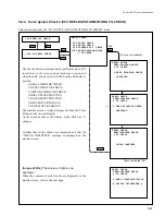
c) C42: RS-232C STATUS
ISR use
Displays the RS-232C port status, and sets the baud rate and flow control
requisite for the ISR.
Setting (Baud rate or Flow control)
(1) Align “*” mark with the item to be set using the search dial(JOG mode).
(2) To display the desire setting, trun the search dial while pressing the JOG
button.
(3) Press the SET button (or switch S300 on the SS board). Setting is then
completed.
The display description is shown below.
1
Selects the buad rate from the followings.
1200, 2400, 4800, 9600, 19.2K (bps)
2
Selects/changes the flow control of transmitting side from the followings.
H/W
;
Hardware control
XOFF
;
XON/XOFF control
H/W,XOFF ;
Both the hardware and XON/XOFF
3
Protcol state indication
ISR x[yyyy...........]
• Displays last correctly recieving command
(Displays former recieving command till ACK
transmitting is completed.)
• Displays the protcol status of the unit.
A ; on ACK transmission
N ; on NAK transmission
T ; on ATN (OPC or QRESP) transmission
W ; waiting for ACK
X ; XOFF received, waiting for XON
4
Device ID is desplayed a name that sets by DEVID command of ISR
protocol.
Even if the power is turned off, this device ID is kept till it changes by
DEVID command.
5
Displays the number of the parity error (PE), framing error (FE), and overrun
error (OE) of receiving data.
6
The number with ( ) indicates the pin number of RS-232C connector.
The four figures (hexadecimal) at TXD or RXD indicates the number of
correctly transmitting or recieving data (byte).
Other items indicates the pin state with ON( > +3 V) or OFF( < –3 V).
When RS-232C port connects with computer &c., normally turns all ON.
When not connected, the state of input pins (CTS, DSR, DCD) are undefined.
Above screen is one example.
OTHERS CHECK MODE
C42:RS-232C STATUS
*BAUD RATE 19.2K
FLOW CONTROL H/W
ISR [ ]
ID [DigiBeta-1 ]
PE 00 FE 00 OE 00
TXD(2)0000 RXD(3)0000
RTS(4) ON CTS(5) ON
DSR(6) ON DCD(8) ON
DTR(20) ON
1
6
2
3
4
5
OTHERS CHECK MODE
C42:RS-232C STATUS
*BAUD RATE 19.2K
FLOW CONTROL H/W
ISR [ ]
ID [DigiBeta-1 ]
PE 00 FE 00 OE 00
TXD(2)0000 RXD(3)0000
RTS(4) ON CTS(5) ON
DSR(6) ON DCD(8) ON
DTR(20) ON
Summary of Contents for DVW-522
Page 6: ......
Page 40: ......
Page 49: ...2 9 2 4 1 Printed Circuit Board Locations Rear view Front view ...
Page 50: ...2 10 Top view of casssette compartment 2 4 1 Printed Circuit Board Locations Top view ...
Page 64: ......
Page 68: ......
Page 82: ......
Page 134: ......
Page 136: ...7 2 7 2 OVERALL 1 4 OVERALL 1 4 7 2 Overall Signal Processing System OVERALL 1 4 DVW 522 522P ...
Page 137: ...7 3 7 3 OVERALL 2 4 OVERALL 2 4 Signal Processing System OVERALL 2 4 DVW 522 522P ...
Page 140: ......


