6-3
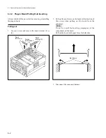
Inserting
4.
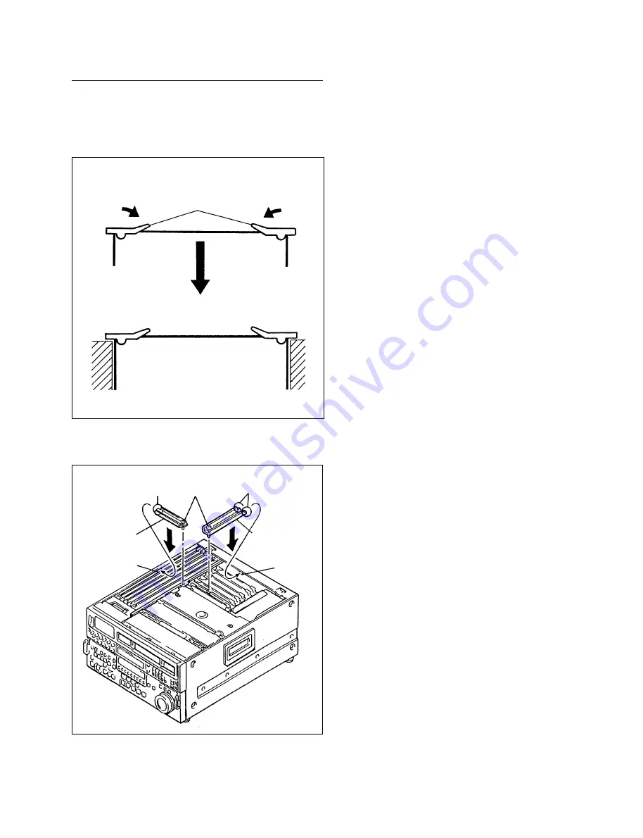
Connect the disconnected harness.
5.
Insert the board after pushing down the eject levers as
shown in the figure.
6.
Insert the protrusion of the board retainer (L) or (S) into
the square hole, and tighten the screw.
6-1. General Information for Boards Replacement
Eject levers
Protrusion
Board
retainer (L)
Board
retainer (S)
Square
hole
Square
hole
Protrusion
Screws
Summary of Contents for DVW-522
Page 6: ......
Page 40: ......
Page 49: ...2 9 2 4 1 Printed Circuit Board Locations Rear view Front view ...
Page 50: ...2 10 Top view of casssette compartment 2 4 1 Printed Circuit Board Locations Top view ...
Page 64: ......
Page 68: ......
Page 82: ......
Page 134: ......
Page 136: ...7 2 7 2 OVERALL 1 4 OVERALL 1 4 7 2 Overall Signal Processing System OVERALL 1 4 DVW 522 522P ...
Page 137: ...7 3 7 3 OVERALL 2 4 OVERALL 2 4 Signal Processing System OVERALL 2 4 DVW 522 522P ...
Page 140: ......

