6-5
6-2-2. 27 MHz FREQ Adjustment
Procedures
STEP 1
1.
Connect the frequency counter to TP1003 on the
VPR-1 board.
2.
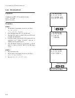
On the menu of maintenance mode, set as follows:
A2: AUDIO/VIDEO ADJUST
A20: VPR VR 0
3.
Adjust at
27 MHz FREQ
.
(When the search dial is turned while pressing the JOG
button, the adjustment data can be changed.)
Specifications: 27,000,000
±
100 Hz
STEP 2
1.
Save adjustment data.
2.
On the menu of maintenance mode, set as follows:
A2F: NV-RAM CONTROL
3.
Execute
SAVE ALL ADJUST DATA.
6-2-3. PB Clock Phase Setting
Procedures
STEP 1
1.
On the menu of maintenance mode, set as follows:
A2: AUDIO/VIDEO ADJUST
A20: VPR VR 0
2.
Setting at
PB CK27 DL
.
(When the search dial is turned while pressing the JOG
button, the setting data can be changed.)
Specifications: DATA “F0”
STEP 2
1.
Save adjustment data.
2.
On the menu of maintenance mode, set as follows:
A2F: NV-RAM CONTROL
3.
Execute
SAVE ALL ADJUST DATA
.
6-2. Adjustment after VPR-1 board replacement
Summary of Contents for DVW-522
Page 6: ......
Page 40: ......
Page 49: ...2 9 2 4 1 Printed Circuit Board Locations Rear view Front view ...
Page 50: ...2 10 Top view of casssette compartment 2 4 1 Printed Circuit Board Locations Top view ...
Page 64: ......
Page 68: ......
Page 82: ......
Page 134: ......
Page 136: ...7 2 7 2 OVERALL 1 4 OVERALL 1 4 7 2 Overall Signal Processing System OVERALL 1 4 DVW 522 522P ...
Page 137: ...7 3 7 3 OVERALL 2 4 OVERALL 2 4 Signal Processing System OVERALL 2 4 DVW 522 522P ...
Page 140: ......


