6-6
A
1
2
3
4
5
6
7
A
1-648-534-
MADE IN JAPAN
1
2
3
4
5
6
7
A
B
B
C
C
D
D
E
E
F
F
G
G
H
H
J
J
K
K
L
L
M
M
N
N
P
P
R
R
APR-1
RV900
RV903
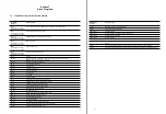
6-3. Adjustment after APR-1 Board
Replacement
6-3-1. CUE Monitor Output Level
Adjustment
Tools
Measuring equipment: Audio analyzer
Procedures
STEP 1
1.
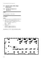
Connect the audio analyzer to MONITOR OUTPUT L/R.
2.
Select “CUE” at the “MONITOR SELECT L/R”.
3.
Play back the 1 kHz, 0 VU signal portion (00:00 -
01:25) of the alignment tape ZR5-1/1P.
ZR5-1
: for NTSC
ZR5-1P : for PAL
4.
Adjustments
MONITOR L:
1
RV900/APR-1(D-4)
MONITOR R:
1
RV903/APR-1(E-4)
Specifications: +4.0
±
0.1 dBu (terminated by 600
Z
)
6-3. Adjustment after APR-1 board replacement
Summary of Contents for DVW-522
Page 6: ......
Page 40: ......
Page 49: ...2 9 2 4 1 Printed Circuit Board Locations Rear view Front view ...
Page 50: ...2 10 Top view of casssette compartment 2 4 1 Printed Circuit Board Locations Top view ...
Page 64: ......
Page 68: ......
Page 82: ......
Page 134: ......
Page 136: ...7 2 7 2 OVERALL 1 4 OVERALL 1 4 7 2 Overall Signal Processing System OVERALL 1 4 DVW 522 522P ...
Page 137: ...7 3 7 3 OVERALL 2 4 OVERALL 2 4 Signal Processing System OVERALL 2 4 DVW 522 522P ...
Page 140: ......


