6-12
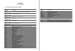
6-6-2. Digital DT System Adjustment
Procedures
STEP 1
1.
On the menu of maintenance mode, set as follows:
A0: SERVO/DT ADJUST
A02: DIGITAL DT ADJUST
A021: DRIVE GAIN
2.
Insert alignment tape ZR5-1/1P into this unit.
ZR5-1
: for NTSC
ZR5-1P : for PAL
3.
Set the “*” mark to
Start auto adjust
using a
search dial (JOG mode).
4.
Press the SET button (or switch S300 on the SS board).
(If the unit has already entered the STILL mode, the
adjustment is initiated.)
5.
The “Push JOG button” message is displayed on the
monitor screen.
Press the JOG button. The unit then enters the STILL
mode to initiate the adjustment.
6.
After adjustment is completed, the “ADJUST
COMPLETE” message is displayed on the monitor
screen.
7.
Press the MENU button (or switch S301 on the SS
board) to return to the DIGITAL DT ADJUST menu
screen.
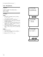
(2) Insert alignment tape
(3) DIAL
(4) SET or S300
(5) JOG
During adjustment
Adjustment completed
(7) MENU or S301
6-6. Adjustment after SS-52 board replacement
DIGITAL DT ADJUST
A021:DRIVE GAIN
MODE : STILL
No operation
*Start auto adjust
Push JOG button
DIGITAL DT ADJUST
A021:DRIVE GAIN
MODE : STILL
No operation
*Start auto adjust
ADJUSTING......
DIGITAL DT ADJUST
A021:DRIVE GAIN
MODE : STILL
No operation
*Start auto adjust
ADJUST COMPLETE
*A023:NV-RAM CONTROL
DIGITAL DT ADJUST
A021:DRIVE GAIN
MODE : STILL
*No operation
Start auto adjust
Summary of Contents for DVW-522
Page 6: ......
Page 40: ......
Page 49: ...2 9 2 4 1 Printed Circuit Board Locations Rear view Front view ...
Page 50: ...2 10 Top view of casssette compartment 2 4 1 Printed Circuit Board Locations Top view ...
Page 64: ......
Page 68: ......
Page 82: ......
Page 134: ......
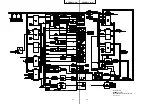
Page 136: ...7 2 7 2 OVERALL 1 4 OVERALL 1 4 7 2 Overall Signal Processing System OVERALL 1 4 DVW 522 522P ...
Page 137: ...7 3 7 3 OVERALL 2 4 OVERALL 2 4 Signal Processing System OVERALL 2 4 DVW 522 522P ...
Page 140: ......


