1-15
5.
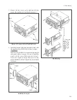
Check that the shaft of the search dial is not seen in the
round hole of the mode selection plate and then tighten
the screw.
Allowing search dial pressing to switch the mode
6.
Perform the steps 1 to 3.
7.
Slide the mode selection plate in the direction indicated
by the arrow until it touches the B portion.
8.
Check that the shaft of the search dial is seen in the
round hole of the mode selection plate and then tighten
the screw.
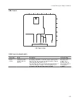
‹Back view›
Mode selection plate
B3
x
14
Round hole
The State that the Mode Cannot Be Switched
The shaft is not seen in the round hole.
1-9. Search Dial Mode Switching
‹Back view›
B3
x
14
B portion
Mode selection plate
The shaft is seen in the round hole.
Search dial shaft
Round hole
The State that the Mode Can Be Switched
Summary of Contents for DVW-522
Page 6: ......
Page 40: ......
Page 49: ...2 9 2 4 1 Printed Circuit Board Locations Rear view Front view ...
Page 50: ...2 10 Top view of casssette compartment 2 4 1 Printed Circuit Board Locations Top view ...
Page 64: ......
Page 68: ......
Page 82: ......
Page 134: ......
Page 136: ...7 2 7 2 OVERALL 1 4 OVERALL 1 4 7 2 Overall Signal Processing System OVERALL 1 4 DVW 522 522P ...
Page 137: ...7 3 7 3 OVERALL 2 4 OVERALL 2 4 Signal Processing System OVERALL 2 4 DVW 522 522P ...
Page 140: ......


