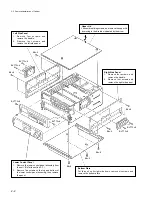
1-17
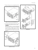
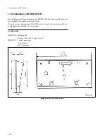
Blank panel installation
1.
Remove the lower control panel assembly.
(Refer to Section 2-7.)
2.
Fix the both arms at an angle of 45
°
.
3.
Set the notches of the blank panel with the claws of the
each arm and tighten two screws until a click sounds.
n
Push the head of the two screws when the hook does
not move smoothly and when the panel is difficult to
set. This facilitates the setting.
Assembling of remote control unit
1.
Pass the connector at the end of the remote cable with a
15-pin connector through the control panel case and
tighten the screw of the cord stopper to fix.
2.
Wind the harness clamper round a cable and fix the
cable so that it does not move.
Fixing of Remote Cable
3.
Loosen the two knob screws at the bottom of the
control panel case by one or two turns.
Turning of Knob Screws
1-10. Installation of BKDW-510/511
Claws
Screw
B3
x
12
Notches
Blank panel
Notches
Screw
B3
x
12
Claws
Installation of Blank Panel
Cable
BV3
x
8
Cord stopper
Control panel case
Harness clamper
Control panel case
Knob screws
Summary of Contents for DVW-522
Page 6: ......
Page 40: ......
Page 49: ...2 9 2 4 1 Printed Circuit Board Locations Rear view Front view ...
Page 50: ...2 10 Top view of casssette compartment 2 4 1 Printed Circuit Board Locations Top view ...
Page 64: ......
Page 68: ......
Page 82: ......
Page 134: ......
Page 136: ...7 2 7 2 OVERALL 1 4 OVERALL 1 4 7 2 Overall Signal Processing System OVERALL 1 4 DVW 522 522P ...
Page 137: ...7 3 7 3 OVERALL 2 4 OVERALL 2 4 Signal Processing System OVERALL 2 4 DVW 522 522P ...
Page 140: ......

