1-19
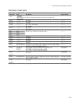
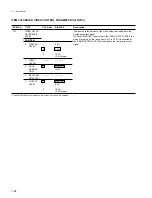
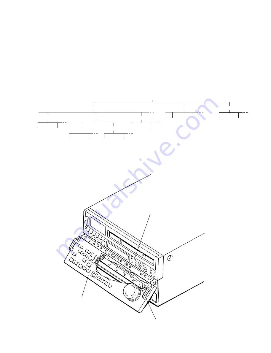
INITIAL SETUP MENU
BANK-3
BANK-2
BANK-1
ITEM-
***
ITEM-
***
ITEM-
***
DATA-0
DATA-1
SUB-0
SUB-1
DATA-0
DATA-1
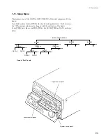
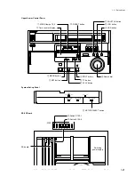
Upper control panel
System set-up panel
Lower control panel
1-11. Setup Menu
The memory area of the INITIAL SETUP MENU of this unit comprises of three
banks.
Each bank contains identical ITEMs which can be independently set. For this reason,
the VTR operation setups can be changed with the switchover of the banks.
Some ITEMs have the several SUB-ITEMs. Each SUB-ITEM has DATA as shown
below.
Name of Each Panels
1-11. Setup Menu
Summary of Contents for DVW-522
Page 6: ......
Page 40: ......
Page 49: ...2 9 2 4 1 Printed Circuit Board Locations Rear view Front view ...
Page 50: ...2 10 Top view of casssette compartment 2 4 1 Printed Circuit Board Locations Top view ...
Page 64: ......
Page 68: ......
Page 82: ......
Page 134: ......
Page 136: ...7 2 7 2 OVERALL 1 4 OVERALL 1 4 7 2 Overall Signal Processing System OVERALL 1 4 DVW 522 522P ...
Page 137: ...7 3 7 3 OVERALL 2 4 OVERALL 2 4 Signal Processing System OVERALL 2 4 DVW 522 522P ...
Page 140: ......


