1-20
1-11. Setup Menu
1
1
1
1
1
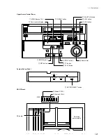
MENU Lamps 1,2,3 (Upper control panel)
The MENU lamps indicate on which bank the VTR
is operating.
The bank that is lighted, is the selected bank at
present.
2
2
2
2
2
Time Counter Display (Lower control panel)
The Time Counter displays the ITEM No., SUB-
ITEM No., and DATA No.
Since the time counter indicates the minimum data
required for modification in the menu mode, the
setup can be modified without viewing the video
monitor.
3
3
3
3
3
MENU Button (Lower control panel)
Use the MENU button to enter and exit the menu
mode.
When this button is pressed while modification of
the setup is in progress, the contents which you have
modified the ITEMs so far are canceled and the unit
exits the setup menu mode.
When this button is pressed again after exiting the
setup menu mode, the unit enters the setup menu
mode again starting from the ITEM that was
displayed before exiting.
4
4
4
4
4
SET Button (Lower control panel)
Press the SET button to store the modified DATA in
the memory bank where the MENU lamp is lit. The
unit exits the menu mode.
5
5
5
5
5
STOP Button (Lower control panel)
Use the STOP button in the setup menu mode to
enter individual displays of the ITEM which has
SUB-ITEMs and select a SUB-ITEM.
Turn the search dial while pressing the STOP button
to select a SUB-ITEM.
6
6
6
6
6
TC Button (Lower control panel)
By pressing this button in the setup menu mode, the
menu jumps to H01 which is the top ITEM of the
menu.
7
7
7
7
7
PLAY Button (Lower control panel)
Use the PLAY button in the menu mode to display
the ITEM-F00 SERIES.
Turn the search dial while pressing the PLAY button
to select an ITEM of the ITEM-F00 SERIES.
8
8
8
8
8
Search Dial (Lower control panel)
Pressing this dial switches between the SHUTTLE
and JOG modes alternately. The SHUTTLE or the
JOG lamp lights accordingly.
When the search dial is in the JOG mode (unclicked
position), the ITEM, SUB-ITEM and DATA can be
modified.
9
9
9
9
9
VAR Button (Lower control panel)
To jump to the top item of the next (or preceding)
category, turn the search dial while pressing this
button.
!/
!/
!/
!/
!/
JOG Button (Lower control panel)
Press the JOG button once so that the search dial
enters the JOG mode, and the JOG lamp lights.
Turn the search dial while pressing the JOG button
to enter individual displays of each ITEM and
modify the data. (The same function as the
SHUTTLE button)
!-
!-
!-
!-
!-
SHUTTLE Button (Lower control panel)
Turn the search dial while pressing the SHUTTLE
button to enter individual displays of each ITEM and
modify the data. (The same function as the JOG
button)
!=
!=
!=
!=
!=
RESET Button (Lower control panel)
Press RESET button in the menu mode, the menu
data (only the memory bank whose the MENU lamp
lights) is all returned to the factory-setting state and
the system exits the menu mode.
![
![
![
![
![
SET UP SELECT Switch (System set-up panel)
When the POWER is turned on, the VTR operates
according to the bank settings selected with this
switch.
When the unit is in the menu mode, the contents of
each bank can be checked, modified and also the
banks can be switched with this switch.
!]
!]
!]
!]
!]
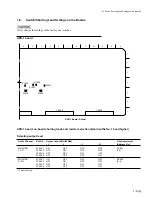
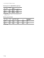
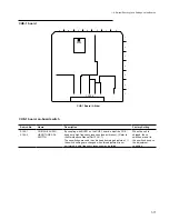
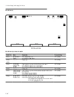
Switch S100-1 (SS-52 Board)
Set this switch to ON (CLOSE) when displaying the
system menu (all the ITEMs from the ITEM-713).
!\
!\
!\
!\
!\
witch S100-5 (SS-52 Board)
Set this switch to ON (CLOSE) when executing the
customize menu mode.
!;
!;
!;
!;
!;
Video Monitor
When the CHARACTER switch on the system setup
panel is set to ON, the information on ITEM, SUB-
ITEM, and DATA is superimposed on the monitor
screen that is connected to the VIDEO OUTPUT
COMPOSITE 2 or RF ADAPTOR VIDEO connector.
Various selector switches are provided on the system setup panel, and printed circuit board. Each mode
can be changed by selecting these switches. Moreover, each mode can be also changed by the operation of
the setup menu described later.
The buttons used in modifying the setup are described below.
Summary of Contents for DVW-522
Page 6: ......
Page 40: ......
Page 49: ...2 9 2 4 1 Printed Circuit Board Locations Rear view Front view ...
Page 50: ...2 10 Top view of casssette compartment 2 4 1 Printed Circuit Board Locations Top view ...
Page 64: ......
Page 68: ......
Page 82: ......
Page 134: ......
Page 136: ...7 2 7 2 OVERALL 1 4 OVERALL 1 4 7 2 Overall Signal Processing System OVERALL 1 4 DVW 522 522P ...
Page 137: ...7 3 7 3 OVERALL 2 4 OVERALL 2 4 Signal Processing System OVERALL 2 4 DVW 522 522P ...
Page 140: ......


