1-23
1-11-2. Details of the Setup Menu
The numbers enclosed in the
under the DATA column
indicate the factory preset settings.
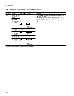
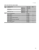
ITEM-H00 SERIES: HOURS METER PARAMETER
ITEM No.
H01
H02
H03
H04
H12
H13
H14
TITLE
OPERATION
HOURS
DRUM RUNNING
HOURS
TAPE RUNNING
HOURS
THREADING
COUNTER
DRUM RUNNING
HOURS
(resettable)
TAPE RUNNING
HOURS
(resettable)
THREADING
COUNTER
(resettable)
DATA No.
DISPLAY
No selection item
No selection item
No selection item
No selection item
No selection item
No selection item
No selection item
Description
The accumulated power ON time is displayed on the timer counter
in 10-hour units.
(NOTE)
The accumulated power ON time is displayed in 1-hour units on
the timer counter while the JOG/SHUTTLE button on the lower
control panel is pressed. However, it is displayed in 1-hour units
on the monitor screen without pressing the JOG/SHUTTLE button.
The accumulated drum running hours while the mechanism stays
in the threading-end position, is displayed on the timer counter in
10-hour units.
(NOTE)
The accumulated drum running hours are displayed in 1-hour units
on the timer counter while the JOG/SHUTTLE button on the lower
control panel is pressed. However, it is displayed in 1-hour units
on the monitor screen without pressing the JOG/SHUTTLE button.
The accumulated tape running hours in the PLAY and SEARCH
modes (except STILL mode) are displayed on the timer counter in
10-hour units.
(NOTE)
The accumulated tape running hours are displayed in 1-hour units
on the timer counter while the JOG/SHUTTLE button on the lower
control panel is pressed. However, it is displayed in 1-hour units
on the monitor screen without pressing the JOG/SHUTTLE button.
The accumulated numbers of threading/unthreading cycle are
displayed on timer counter in 10-cycle units.
(NOTE)
The accumulated numbers of the threading/unthreading cycle are
displayed in the actual number of cycles on the timer counter while
the JOG/SHUTTLE button on the lower control panel is pressed.
However it is displayed in the actual number of cycles on the
monitor screen without pressing the JOG/SHUTTLE button.
The display content is the same as that of ITEM H02. But the
ITEM H12 is resettable in the maintenance mode. (Refer to
Section 5 MAINTENANCE MODE.)
The display content is the same as that of ITEM H03. But the
ITEM H13 is resettable in the maintenance mode. (Refer to
Section 5 MAINTENANCE MODE.)
The display content is the same as that of ITEM H04. But ITEM
H14 is resettable in the maintenance mode. (Refer to Section 5
MAINTENANCE MODE.)
1-11. Setup Menu
Summary of Contents for DVW-522
Page 6: ......
Page 40: ......
Page 49: ...2 9 2 4 1 Printed Circuit Board Locations Rear view Front view ...
Page 50: ...2 10 Top view of casssette compartment 2 4 1 Printed Circuit Board Locations Top view ...
Page 64: ......
Page 68: ......
Page 82: ......
Page 134: ......
Page 136: ...7 2 7 2 OVERALL 1 4 OVERALL 1 4 7 2 Overall Signal Processing System OVERALL 1 4 DVW 522 522P ...
Page 137: ...7 3 7 3 OVERALL 2 4 OVERALL 2 4 Signal Processing System OVERALL 2 4 DVW 522 522P ...
Page 140: ......


