1-25
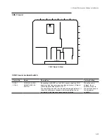
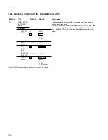
+3
-3
RVS
RVS
FWD
FWD
+1
-1
+3
-3
RVS
RVS
FWD
FWD
Description
Select how the unit enters the search mode.
0:
The unit enters the search mode by turning the search dial in all
modes.
1:
The unit enters the search mode by pressing search button.
Select the tape speed (VTR command) characteristics which
correspond to the JOG dial rotation.
0:
Tape speed changes with linear characteristics in the range
from –1 to +1 times normal tape speed.
1:
Tape speed changes with flight of steps characteristics in the
range from –3 to +3 times normal tape speed as shown in the
TYPE 2. (This characteristics has the flat response where tape
speed does not change regardless the JOG dial rotation in the
range of
±
1 times normal tape speed.)
2:
Tape speed changes with linear characteristics in the range
from –3 to +3 times normal tape speed as shown in the TYPE 3.
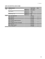
ITEM No.
011
012
TITLE
CHARACTER
V-SIZE
CONDITION
DISPLAY ON
VIDEO
MONITOR
DATA No.
01
02
03
04
0
1
DISPLAY
x
1
x
2
x
3
x
4
disable
enable
Description
Select the vertical size of characters such as time code that are
superimposed in the VIDEO OUTPUT-2 and RF ADAPTOR VIDEO
connectors.
01: Standard size
02: Twice the standard size
03: Three times the standard size
04: Four times the standard size
Select whether or not to additionally display the channel condition to
the superimposing video characters.
0:
Does not display the condition
1:
Displays the condition
How the Displayed the Channel Condition
The condition is displayed below the timer or status line of the video
characters.
(Example) V– – – A– – –
The four characters following “V” display each video channel
condition between Ach and Dch of the rotary head.
The four characters following “A” display each audio channel
condition between Ach and Dch of the rotary head.
Character pattern
(Space): Status in which no condition is displayed on the front
panel.(STBY OFF, etc.)
–:
The condition is good.
(The front panel display corresponds to green.)
*
:
The condition is no so good.
(The front panel display corresponds to yellow.)
:
The condition is bad.
(The front panel display corresponds to red.)
ITEM-100 SERIES: OPERATIONAL PANEL PARAMETER
TITLE
SELECTION
FOR SEARCH
DIAL ENABLE
JOG DIAL
RESPONSE
DISPLAY
dial direct
via search key
type 1: –1 to +1
type 2: –3 to +3
type 3: –3 to +3
TYPE2
TYPE3
SPEED
SPEED
DATA No.
0
1
0
1
2
ITEM No.
101
116
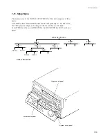
1-11. Setup Menu
ROTATION
ROTATION
Summary of Contents for DVW-522
Page 6: ......
Page 40: ......
Page 49: ...2 9 2 4 1 Printed Circuit Board Locations Rear view Front view ...
Page 50: ...2 10 Top view of casssette compartment 2 4 1 Printed Circuit Board Locations Top view ...
Page 64: ......
Page 68: ......
Page 82: ......
Page 134: ......
Page 136: ...7 2 7 2 OVERALL 1 4 OVERALL 1 4 7 2 Overall Signal Processing System OVERALL 1 4 DVW 522 522P ...
Page 137: ...7 3 7 3 OVERALL 2 4 OVERALL 2 4 Signal Processing System OVERALL 2 4 DVW 522 522P ...
Page 140: ......

