2-1
2-2. Removal/Installation of Cabinet
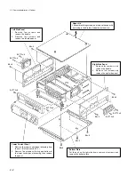
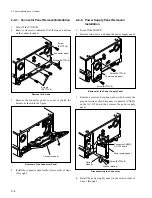
2-2-1. Cabinet Removal/Installation
c
Always switch off the POWER before removing and
installing cabinet.
Upper Control Panel
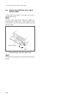
1.
Remove the upper lid.
2.
Remove the control knob on the upper control panel.
3.
Remove the each one screw on the left and right sides.
4.
Fingers should be inserted in the space between the
upper control panel and chassis, and remove the upper
control panel as shown in the figure A.
5.
When installing, insert the projections of the upper control
panel into the holes of the chassis, then fix the panel with
the screws as shown in the figure B.
Screw
(BVTT3
x
6)
Section 2
Service Overview
2-1. Notes on Power Supply Block
2-1-1. Warning on Primary Circuit and
Electric Shock
The power supply block consists of the AC-139 board and
primary peripheral components. The whole AC-139 board
is on the primary side circuit, so pay careful attention to the
electric shock. Since the inside of a switching regulator is
also on the primary side circuit, treat it with care.
2-1-2. Notes on Resetting the Circuit
Breaker
When the breaker on the power supply panel is activated
and the button is ejected, remove the cause of the trouble,
then push the button.
Control knob
Upper control panel
<Fig. A>
<Fig. B>
Screw
(BVTT3
x
6)
Screw
(BVTT3
x
6)
Chassis
Screw
(BVTT3
x
6)
Upper control panel
Projection
Projection
Summary of Contents for DVW-522
Page 6: ......
Page 40: ......
Page 49: ...2 9 2 4 1 Printed Circuit Board Locations Rear view Front view ...
Page 50: ...2 10 Top view of casssette compartment 2 4 1 Printed Circuit Board Locations Top view ...
Page 64: ......
Page 68: ......
Page 82: ......
Page 134: ......
Page 136: ...7 2 7 2 OVERALL 1 4 OVERALL 1 4 7 2 Overall Signal Processing System OVERALL 1 4 DVW 522 522P ...
Page 137: ...7 3 7 3 OVERALL 2 4 OVERALL 2 4 Signal Processing System OVERALL 2 4 DVW 522 522P ...
Page 140: ......


