2-4
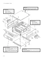
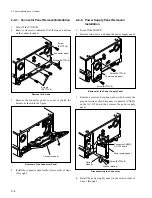
Power supply panel
Connector(CN002)/
AC-139 board
Spring
washer
Ground terminal
Screw(BVTT4
x
8)
Screw(BVTT3
x
6)
Power supply panel
Screw(BVTT3
x
6)
2-2-3. Connector Panel Removal/Installation
1.
Turn off the POWER.
2.
Remove six screws indicated
→
at the top and bottom
on the connector panel.
Removal of Screws
3.
Remove the connector panel so as not to stretch the
harness as shown in the figure.
Removal of the Connector Panel
4.
Install the connector panel in the reverse order of steps
1 through 3.
Connector panel
Connector panel
Screw
(BVTT3
x
6)
Screws(BVTT3
x
6)
Screws
(BVTT3
x
6)
2-2-4. Power Supply Panel Removal/
Installation
1.
Turn off the POWER.
2.
Remove two screws, and open the power supply panel.
Removal of the Power Supply Panel
3.
Remove a screw and a spring washer which secure the
ground terminal, then disconnect connector (CN002)
on the AC-139 board, then remove the power supply
panel.
Disconnecting the Connector
4.
Install the power supply panel in the reverse order of
steps 1 through 3.
2-2. Removal/Installation of Cabinet
Summary of Contents for DVW-522
Page 6: ......
Page 40: ......
Page 49: ...2 9 2 4 1 Printed Circuit Board Locations Rear view Front view ...
Page 50: ...2 10 Top view of casssette compartment 2 4 1 Printed Circuit Board Locations Top view ...
Page 64: ......
Page 68: ......
Page 82: ......
Page 134: ......
Page 136: ...7 2 7 2 OVERALL 1 4 OVERALL 1 4 7 2 Overall Signal Processing System OVERALL 1 4 DVW 522 522P ...
Page 137: ...7 3 7 3 OVERALL 2 4 OVERALL 2 4 Signal Processing System OVERALL 2 4 DVW 522 522P ...
Page 140: ......


