2-5
2-3. Cassette Compartment Removal/
Installation
Removal
1.
Press the EJECT button with the power on.
2.
Turn off the POWER.
3.
Remove the upper lid.
(Refer to Section 2-2-1. )
4.
Remove the plate MD assembly.
(Refer to Section 2-2-2.)
5.
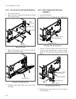
Loosen two screws, and remove the cassette
compartment bracket assembly.
6.
Disconnect the connector (CN930) on the CL-29
board.
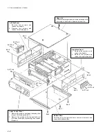
Removal of the Bracket Assembly
7.
Remove the four legs of the cassette compartment for
fixing the position by lifting the cassette compartment
slightly and straight with
A
portions (two portions)
held.
8.
Remove the cassette compartment by sliding up it
raising up the rear part with the
B
portion held as
shown in the figure.
n
In this time, do not move the cassette compartment to
right and left and do not widen the right and left side
panels. If the right and left side panels are widened, a
gear position might be changed or some parts might be
removed.
Removal of the Cassette Compartment
9.
When putting the removed cassette compartment
outside of the unit, make the four legs for fixing
position faced down.
(Because the flexible card wire might be get damaged
if the cassette lid is faced down.)
Bracket assembly
Connector
(CN930)
Cassette compartment
Left side panel
Right side panel
B3
x
6
(with stopper)
2-3. Cassette Compartment Removal/Installation
Summary of Contents for DVW-522
Page 6: ......
Page 40: ......
Page 49: ...2 9 2 4 1 Printed Circuit Board Locations Rear view Front view ...
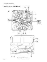
Page 50: ...2 10 Top view of casssette compartment 2 4 1 Printed Circuit Board Locations Top view ...
Page 64: ......
Page 68: ......
Page 82: ......
Page 134: ......
Page 136: ...7 2 7 2 OVERALL 1 4 OVERALL 1 4 7 2 Overall Signal Processing System OVERALL 1 4 DVW 522 522P ...
Page 137: ...7 3 7 3 OVERALL 2 4 OVERALL 2 4 Signal Processing System OVERALL 2 4 DVW 522 522P ...
Page 140: ......

