2-6
Installation
10. Set the harness of the connector (CN930) disconnected
in step 6 so it is not put between chassis.
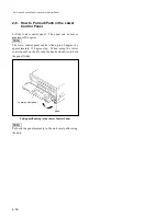
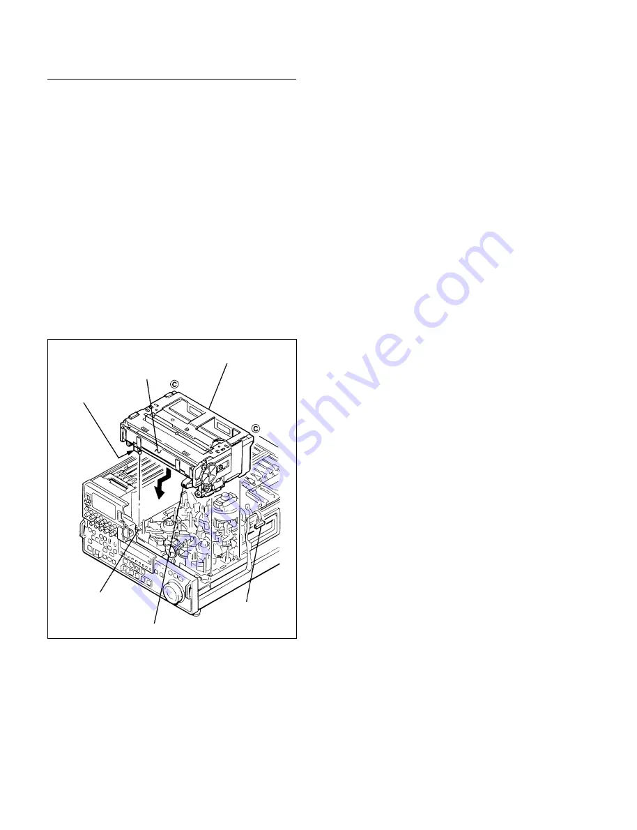
11. Install the cassette compartment inserting slantingly in
the direction as shown in the figure.
12. Insert the four legs of the cassette compartment for
fixing the position into the four holes of the mechanical
chassis for fixing the position by pressing the
C
portions (two portions) as shown in the figure.
13. After confirming that the cassette compartment is fixed
to the chassis, install the cassette compartment bracket
assembly.
n
When looked down on from the top, check that the two
leaf springs are pressed by the two projections on the
cassette compartment.
14. Connect the connector (CN930) on the CL-29 board.
Installation of the Cassette Compartment
Leg for fixing
position
Cassette lid
Connector
(CN930)
Flexible card wire
Hole for fixing
position
Cassette compartment
2-3. Cassette Compartment Removal/Installation
Summary of Contents for DVW-522
Page 6: ......
Page 40: ......
Page 49: ...2 9 2 4 1 Printed Circuit Board Locations Rear view Front view ...
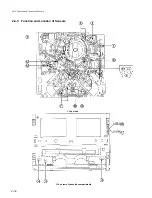
Page 50: ...2 10 Top view of casssette compartment 2 4 1 Printed Circuit Board Locations Top view ...
Page 64: ......
Page 68: ......
Page 82: ......
Page 134: ......
Page 136: ...7 2 7 2 OVERALL 1 4 OVERALL 1 4 7 2 Overall Signal Processing System OVERALL 1 4 DVW 522 522P ...
Page 137: ...7 3 7 3 OVERALL 2 4 OVERALL 2 4 Signal Processing System OVERALL 2 4 DVW 522 522P ...
Page 140: ......


