2-11
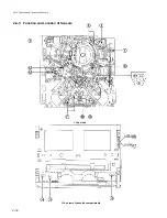
2-4-2. Main Mechanical Part Locations
2-4-2. Main Mechanical Part Locations
!]
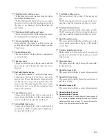
T worm wheel
!\
Worm gear
!;
Drive gear
!'
S worm wheel
!,
S brake assembly
!.
S reel table
@-
S tension regulator arm
@=
TG-0 tape guide
@[
Capstan shaft
@]
Cleaning roller block
@\
Pinch press block
@;
TG-4 tape guide
@'
Threading gear block
1
Audio/TC head
2
TG-3 tape guide
3
Head drum
4
Threading ring
5
T tension regulator arm
6
CTL head
7
TG-2 tape guide
8
Audio/TC head cleaner
9
T drawer arm
!/
TG-10 tape guide
!-
Pinch roller
!=
T reel table


