3-1
Section 3
Error Messages
Code
01
02
03
04
05
06
07
08
09
Description
The slack of the tape is detected during
threading or unthreading, and then tape
protection is done.
The slack or breaking of the tape is
detected in search, fast forward, or rewind
mode, and then tape protection is done.
The slack or breaking of the tape is
detected in playback mode, or either of the
lock of the supply or take-up reel is
detected, and then tape protection is done.
It is detected that the tape does not run at
the speed of designation in fast forward or
rewind mode, and then tape protection is
done.
It is detected that the supply or take-up reel
cannot stop with a cassette is not inserted,
or detected that over current has been
flowing to supply and take-up reels.
When excessive tension is detected, tape
protection is done.
It is detected that the tape does not run at
the speed of designation in play or search
mode, and tape protection is done.
It is detected that drum motor rotation is not
normal, and then tape protection is done.
It is detected that threading or unthreading
is not completed, and then tape protection
is done.
Detection
Detected when the ratio of the FG
frequency at a supply reel, take-up reel
and threading motor is less than the
specified value.
Detected when the ratio of the FG
frequency at a supply reel and take-up
reel is less than the specified value.
Detected when the FG frequency at a
supply or take-up reel is zero (0), or when
the tension detected from a tension
sensor is less than 15 g.
Depends on the comparison between the
tape speed using the FG frequency at
supply and take-up reels and the
designated speed.
Detected using the FG frequency or
current at supply and/or take-up reels.
Detected when the tension detected from
a tension sensor is more than 55 g.
Detected at the tape speed detected from
the FG frequency at a capstan motor.
Detected when the drum speed obtained
from the speed FG of the drum motor is
less than the specified value.
Detected when threading or unthreading
is not completed within ten seconds after
it is started.
3-1. Error Message
This unit features self-diagnostics.
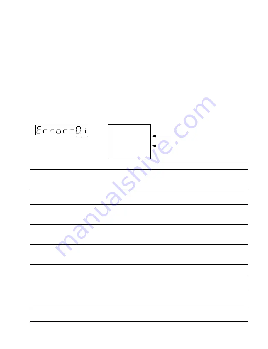
When trouble is detected, an error code is displayed immediately in the time counter
display on the lower control panel, an error code and message are superimposed on
the video monitor connected to the VIDEO OUTPUT COMPOSITE 2 connector and
the RF ADAPTOR VIDEO connector.
Furthermore, as for the interface error (error code 92, 93, 96 and 98), interface object
which error occurred replaced by sub error massage on the video monitor.
( To display error code and massage on the video monitor, the CHARACTER switch
on the system setup panel must be set to ON. )
Time counter display
Video monitor display
Error message
REEL TROUBLE-1
REEL TROUBLE-2
REEL TROUBLE-3
REEL TROUBLE-4
REEL TROUBLE-5
TAPE TENSION ERROR
CAPSTAN TROUBLE
DRUM TROUBLE
TH/UNTH MOTOR TIME OUT
(Continue)
Error code
Code
Error message
E R R O R - 0 1
R E E L T R O U B L E - 1
Summary of Contents for DVW-522
Page 6: ......
Page 40: ......
Page 49: ...2 9 2 4 1 Printed Circuit Board Locations Rear view Front view ...
Page 50: ...2 10 Top view of casssette compartment 2 4 1 Printed Circuit Board Locations Top view ...
Page 64: ......
Page 68: ......
Page 82: ......
Page 134: ......
Page 136: ...7 2 7 2 OVERALL 1 4 OVERALL 1 4 7 2 Overall Signal Processing System OVERALL 1 4 DVW 522 522P ...
Page 137: ...7 3 7 3 OVERALL 2 4 OVERALL 2 4 Signal Processing System OVERALL 2 4 DVW 522 522P ...
Page 140: ......


