5-5
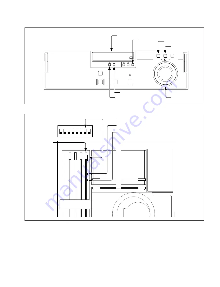
Lower Control Panel
Switch Position on SS Board
O N
1
2
3
4
5
6
7
8
1
Time counter
4
CTL button
6
JOG button
5
SHUTTLE button
7
Search dial
3
SET button
2
MENU button
Switching
power supply
Drum
S100
SS board
!/
S100-7 : MAINTENANCE MODE ACCESS ENABLE switch
9
S301
: DIAG/ ADJUST 2 switch(ADJ–)
8
S300
: DIAG/ ADJUST 1 switch(ADJ+)
SET UP
MENU
SET
U-BIT
TC
CTL
COUNTER
STNDBY
SERVO
EJECT
PLAY
STOP
RESET
SHUTTLE
JOG
VAR
REVERSE
FORWARD
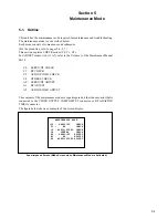
5-1. Outline
Summary of Contents for DVW-522
Page 6: ......
Page 40: ......
Page 49: ...2 9 2 4 1 Printed Circuit Board Locations Rear view Front view ...
Page 50: ...2 10 Top view of casssette compartment 2 4 1 Printed Circuit Board Locations Top view ...
Page 64: ......
Page 68: ......
Page 82: ......
Page 134: ......
Page 136: ...7 2 7 2 OVERALL 1 4 OVERALL 1 4 7 2 Overall Signal Processing System OVERALL 1 4 DVW 522 522P ...
Page 137: ...7 3 7 3 OVERALL 2 4 OVERALL 2 4 Signal Processing System OVERALL 2 4 DVW 522 522P ...
Page 140: ......


