5-7
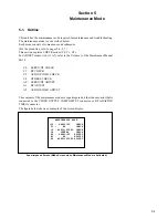
A0:SERVO/DT ADJUST
(Refer to the Volume 1 of the
Maintenance Manual Part 2)
A00-01:SERVO ADJUST
A000:A001-008 ADJ.
A001:S REEL FG DUTY
A002:T REEL FG DUTY
A003:CAPSTAN FG DUTY
A004:S REEL OFFSET/FRICTION
A005:T REEL OFFSET/FRICTION
A006:S REEL TORQUE
A007:T REEL TORQUE
A008:S/T TENSION OFFSET
A010:CAPSTAN FREE SPEED
A011:RF SWITCHING POS.
A012:NV-RAM CONTROL
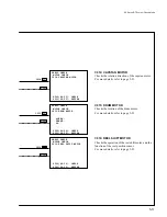
A02:DIGITAL DT ADJUST
A020:CAPSTAN FG LEVEL
A021:DRIVE GAIN
A022:HEAD OFFSET LEVEL
A023:NV-RAM CONTROL
A1:RF ADJUST
(Refer to the Volume 1 of the
Maintenance Manual Part 2)
A10:A11-A17 ADJUST
A11:PLAY PLL
A12:ADV EQUALIZER
A14:SHUTTLE FWD PLL
A15:SHUTTLE REV PLL
A16:VAR FWD PLL
A17:VAR REV PLL
A19:ADV LEVEL
A1F:NV-RAM CONTROL
A2:AUDIO/VIDEO ADJUST
(Refer to the Volume 1 of the
Maintenance Manual Part 2)
A20:VPR VR 0
A2F:NV-RAM CONTROL
5-1. Outline
Summary of Contents for DVW-522
Page 6: ......
Page 40: ......
Page 49: ...2 9 2 4 1 Printed Circuit Board Locations Rear view Front view ...
Page 50: ...2 10 Top view of casssette compartment 2 4 1 Printed Circuit Board Locations Top view ...
Page 64: ......
Page 68: ......
Page 82: ......
Page 134: ......
Page 136: ...7 2 7 2 OVERALL 1 4 OVERALL 1 4 7 2 Overall Signal Processing System OVERALL 1 4 DVW 522 522P ...
Page 137: ...7 3 7 3 OVERALL 2 4 OVERALL 2 4 Signal Processing System OVERALL 2 4 DVW 522 522P ...
Page 140: ......


