5-10
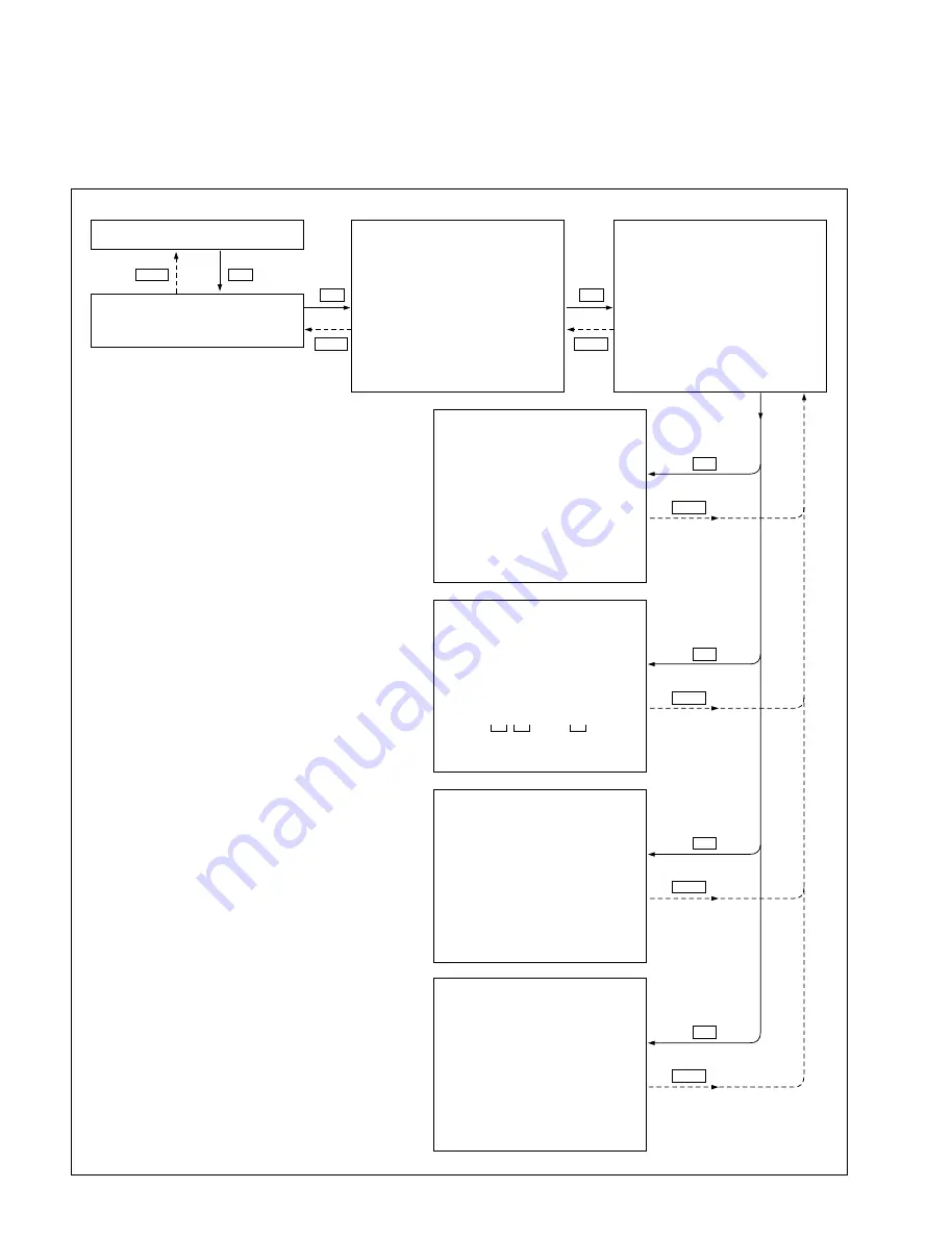
5-2-1. Servo System Check 1 (C00: INPUT CHECK)
This section describes the “C00: INPUT CHECK” mode.
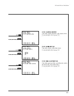
C000: CASSETTE SW
Checks the functions of the cassette tab
sensors and REC inhibit sensors.
For more details, refer to page 5-11.
C001: CASSETTE COMP. SW
Checks the functions of the sensors in the
compartment block.
For more details, refer to page 5-12.
C002: TOP/END SENSOR
Checks the functions of the tape top and end
sensors.
For more details, refer to page 5-14.
C003: DEW SENSOR
Checks the function of the DEW
(condensation detection) sensor.
For more details, refer to page 5-15.
SERVO CHECK
*C00:INPUT CHECK
C01:MOTOR CHECK
C02:PLUNGER SOL. CHECK
C03:REEL/CAPSTAN MOTOR
& FG CHECK
C000
*C0:SERVO/DT CHECK
*C00-04:SERVO CHECK
SERVO CHECK
INPUT CHECK
*C000:CASSETTE SW
C001:CASSTE COMP. SW
C002:T REEL BRAKE
C003:CLEANING ROLLER
SERVO CHECK
INPUT CHECK
C000:CASSETTE SW
1:REEL HUB 2:METAL/OX
3:THICKNESS 4:SPARE
5:SPARE 6:DGTL/ANLG
7:N.A. 8:N.A.
123
SW 87654321 4 5
00000000 6
C001
SERVO CHECK
INPUT CHECK
C001:CASSETTE COMP. SW
SW1: CASSETTE IN SW 1
SW2: CASSETTE IN SW 2
SW3: LARGE CASSETTE SW
3 1 2
C002
SERVO CHECK
INPUT CHECK
C002:TOP/END SENSOR
END TOP
SENSOR SENSOR
OFF OFF
C003
SERVO CHECK
INPUT CHECK
C003:DEW SENSOR
DEW SENSOR : DRY
C00
SET
MENU
SET
MENU
SET
MENU
SET
SET
MENU
SET
MENU
SET
MENU
MENU
5-2. Servo/DT System Check Mode
Summary of Contents for DVW-522
Page 6: ......
Page 40: ......
Page 49: ...2 9 2 4 1 Printed Circuit Board Locations Rear view Front view ...
Page 50: ...2 10 Top view of casssette compartment 2 4 1 Printed Circuit Board Locations Top view ...
Page 64: ......
Page 68: ......
Page 82: ......
Page 134: ......
Page 136: ...7 2 7 2 OVERALL 1 4 OVERALL 1 4 7 2 Overall Signal Processing System OVERALL 1 4 DVW 522 522P ...
Page 137: ...7 3 7 3 OVERALL 2 4 OVERALL 2 4 Signal Processing System OVERALL 2 4 DVW 522 522P ...
Page 140: ......

