background image

9

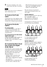
Attachment and Connections

2

Fasten four mounting screws of the 
receiver/tuner unit with a screwdriver.


If any of the screws are loose, malfunction 
due to vibration may occur.

To Connect the Power 
Cable

Using the DC power cable supplied with the 
DWA-F01D, connect the DC IN connector 
to the DC OUT connector of the camcorder.

To Connect the Audio 
Cables

For analog audio

Connect the OUTPUT 1 or OUTPUT 2 
connector on the DWA-F01D to the 
AUDIO IN connectors on the camcorder or 
connected device.

For connected devices that accept 
digital audio input

Connect the AES/EBU OUT connector on 
the DWA-F01D to the digital input 
connector on the connected device using a 
75 

Ω

 BNC cable.

On Connecting Word Clock 
Sync Signal and Digital 
Audio Signal

The DWR-S01D attached to the DWA-F01D 
and the device connected to the DWA-F01D 
through the digital audio interface can be 
operated properly, under either of the 
following conditions:
• The device that is connected to the 

AES/EBU OUT connector of the 
DWA-F01D is equipped with a sampling 
rate converter.

• The DWR-S01D is synchronized with 

the device that is connected to the 

DWA-F01D using the master word clock 
signal input to the WORD SYNC IN 
connector of the DWA-F01D.

There are two types of systems for 
synchronization using the master word 
clock signal.

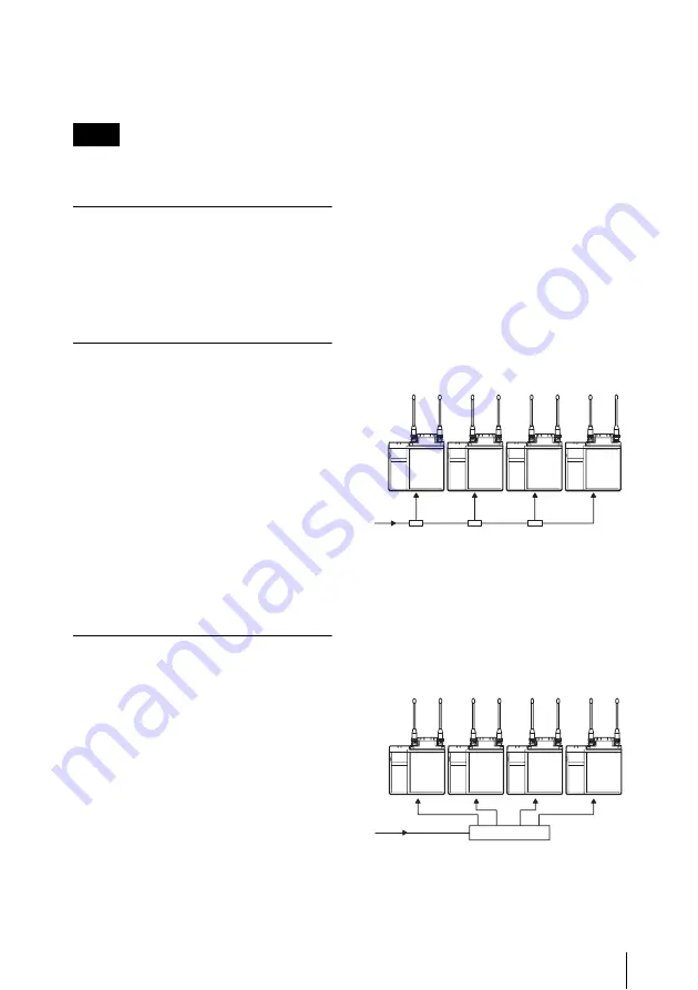
System example 1

The master word clock signal is split using 
the T-shaped BNC splitter.
One of the devices including the 
DWR-S01D must be terminated.

For details on how to terminate the word sync signal 
on the DWR-S01D, refer to the Operating 
Instructions supplied with the DWR-S01D.

a) 75-ohm termination setting: OFF
b) 75-ohm termination setting: ON
c) Master word clock signal

System example 2

The master word clock signal is supplied to 
each device using the distributor. All the 
devices must be terminated.

a) 75-ohm termination setting: ON
b) Master word clock signal
c) Word sync signal distributor

Note

a)

a)

a)

b)

c)

c)

b)

a)

a)

a)

a)

Summary of Contents for DWA-F01D

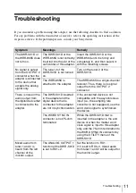
Page 1: ...4 292 344 11 1 2011 Sony Corporation Wireless Adapter Operating Instructions Before operating the unit please read this manual thoroughly and retain it for future reference DWA F01D ...

Page 2: ...ient or relocate the receiving antenna Increase the separation between the equipment and receiver Connect the equipment into an outlet on a circuit different from that to which the receiver is connected Consult the dealer or an experienced radio TV technician for help You are cautioned that any changes or modifications not expressly approved in this manual could void your authority to operate this...

Page 3: ...ry 7 Removing the Battery 8 Attachment and Connections 8 Attaching the Receiver Tuner Unit 8 To Connect the Power Cable 9 To Connect the Audio Cables 9 On Connecting Word Clock Sync Signal and Digital Audio Signal 9 Block Diagram 10 Troubleshooting 11 Important Notes on Operation 13 Notes on Using the Adapter 13 On Cleaning 13 Specifications 14 ...

Page 4: ...DWA F01D comes equipped with a wide range of interfaces One of the analog audio output connectors can be set to output the AES EBU digital format signal A word sync input connector is provided for diverse operational needs Monitor output A monitor output connector is provided to offer easy monitoring of the audio output Parts Identification Front Top Right Sides a DC IN external power input remain...

Page 5: ...TUNER 2 will be output When a WRR 855S is installed this connector does not function d Wireless receiver screw holes Run in the mounting screws to secure the receiver tuner unit e Battery connector Insert a battery e g NP F570 here The InfoLithium L Series is supported If a battery and an external power supply are connected at the same time the external power supply will be used The DWA F01D canno...

Page 6: ...n when the 75 ohm termination has been added on the DWR S01D this connector still works as the high impedance input connector while the DWR S01D is turned off c Monitor volume adjuster Adjusts the audio volume for monitor output Adjustment is enabled only when PHONES is selected with the output selector switch d Output selector switch Selects the output of the OUTPUT 1 2 connector PHONES Allows yo...

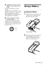
Page 7: ... DC IN external power input connector 4 pin Connect to the external power output connector of the camcorder using the supplied DC power cable This connector accepts the power voltage between 10 V DC and 17 V DC Using a Battery Inserting the Battery 1 Align the grooves on the battery with the guides on the compartment and push down the battery stopper 2 Slide the battery into the compartment while ...

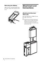
Page 8: ...rection of the arrow Attachment and Connections Attaching the Receiver Tuner Unit Insert the DWR S01D or WRR 855S into the wireless receiver slot 1 Insert the receiver tuner unit into the wireless receiver slot after observing the direction of the D sub 15 pin connector inside the slot and that of the receiver tuner unit ...

Page 9: ...an be operated properly under either of the following conditions The device that is connected to the AES EBU OUT connector of the DWA F01D is equipped with a sampling rate converter The DWR S01D is synchronized with the device that is connected to the DWA F01D using the master word clock signal input to the WORD SYNC IN connector of the DWA F01D There are two types of systems for synchronization u...

Page 10: ...10 Block Diagram Block Diagram Step down transformer DC DC converter Volume Step down transformer ...

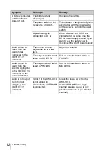
Page 11: ...The WRR 855S is a single channel receiver Thus there is no signal output from the OUTPUT 2 connector There is noise in the audio output from the digital device that is connected to the adapter The DWR S01D inserted in the adapter and the digital device that is connected to the adapter are not in synchronization If the connected device is not compatible with the asynchronous input i e the sampling ...

Page 12: ... headphones connected to the OUTPUT 1 2 connector The monitor volume adjuster is set to a low level Adjust the volume The output selector switch is set to MIC LEVEL Set the output selector switch to PHONES Audio cannot be heard from the recorder connected to the OUTPUT 1 2 connector or the audio is distorted The output selector switch is set to PHONES Set the output selector switch to MIC LEVEL Au...

Page 13: ...ject to an active gas clean its surface as well as the connectors with a dry soft cloth soon after use Lengthy use of the adapter in such places or not cleaning it after its use in such places may shorten its life Clean the surface and the connectors of the adapter with a dry soft cloth Never use thinner benzene alcohol or any other chemicals since these may mar the finish To prevent electromagnet...

Page 14: ...TPUT 1 2 unused DWR S01D CH1 CH2 ON wireless remote control function OFF auto switch for display set to AUTO DIMMER Operating temperature 0 C to 50 C 32 F to 122 F Storage temperature 20 C to 60 C 4 F to 140 F Dimensions unit mm inches excluding protrusions Mass Approx 400 g 14 oz excluding receiver and battery Supplied accessories DC power cable for 4 pin connector 1 Operating Instructions 1 Warr...

Page 15: ...Sony Corporation ...

Reviews: