
C:\_Sony\101003076_DWRR01D\101003076_4177125131_GB\4177125131\4177125131DWRR0
1DUC\GB13CV4-UC.fm
masterpage:Left
DWR-R01D
4-177-125-11 (1)
Sony Corporation
Printed in Japan
Digital Wireless
Receiver
C:\_Sony\PT13K063_DWR-
R01DR02D\PT13K063_4177125171_GB\4177125171\4177125171DWRR01DUC\GB01COV-
UC.fm
masterpage:Right
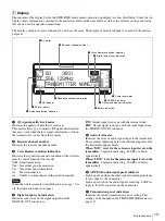
Operating Instructions
Before operating the unit, please read this manual thoroughly
and retain it for future reference.
DWR-R01D
DWR-R01D
4-177-125-
17
(1)
4-177-125-
17
(1)
© 2010 Sony Corporation
The supplied CD-ROM includes Operating Instructions for the DWR-R01D Digital
Wireless Receiver (English, Japanese, French, German, Italian, and Spanish
versions) and the frequency lists (English and Japanese versions) in PDF format.
For more details, see
“Using the CD-ROMs” on page 10.
GB01COV-UC.book Page 1 Thursday, December 12, 2013 1:01 PM
DWR-R01D
4-177-125-
16
(1)
Summary of Contents for DWR-R01D
Page 44: ...44 Carrier Frequencies and Channel Steps ...
Page 45: ......


