Chapter 3 Connections and Settings
83
Chapter 3 Connections and Settings
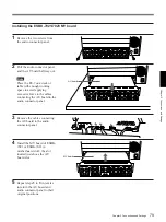
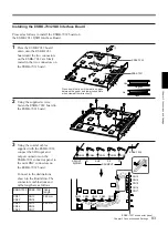
Installing the ESBK-7032 SDI Interface Board
Proceed as follows to install the ESBK-7032 board on
the ESBK-7031 QSDI Interface Board.
1
Press the ESBK-7032 board
down onto the ESBK-7031
board until the two connectors
on the ESBK-7032 are firmly
seated in the two connectors on
the ESBK-7031 board.
2
Using the supplied screws,
fasten the ESBK-7032 board to
the ESBK-7031 board.
3
Using the coaxial cables
supplied with the ESBK-7032,
connect the SDI input and
output connectors on the
ESBK-7031 connector panel to
the mini BNC connectors on
the ESBK-7032 board.
Connect to the destinations
shown in the illustration. The
connector combinations and
calbe length are as follows.
Press down firmly until there are no gaps
between the upper and lower connectors
when viewed from direction
1
.
ESBK-7032
ESBK-7031
Yes
No
No gaps
Gaps
1
SDI OUT
R(PGM)
R
AUX
P2
P1
SDI INPUT
CN35
CN34
CN33
CN32
CN31
CN13
CN14
CN15
CN16
CN17
CN35
CN34
CN33
CN32
CN31
ESBK-7032 ESBK-7031 Cable
length
CN31
CN32
CN13
CN14
380 mm
CN33
CN34
CN35
CN15
CN16
CN17
580 mm
ESBK-7032
ESBK-7031’s connector panel

