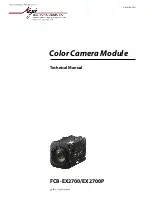
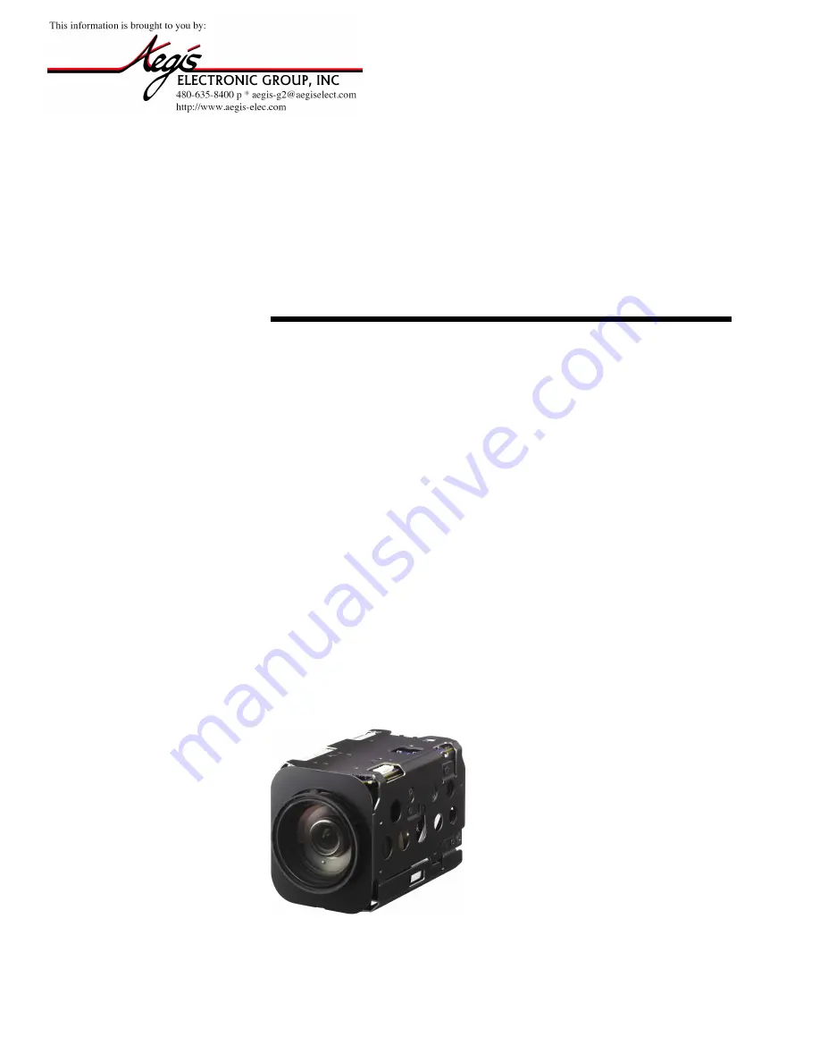
background image

 2013 Sony Corporation


FCB-EH6500(GB)   A-EEP-100-11(1)

Color Camera Module

FCB-EX2700/EX2700P

A-ES4-100-

11

(1)

Technical Manual

Summary of Contents for FCB-EX2700

Page 1: ... 2013 Sony Corporation Color Camera Module FCB EX2700 EX2700P A ES4 100 11 1 Technical Manual ...

Page 2: ...e 22 Spectral Sensitivity Characteristics 22 Key Switch Circuitry 23 Key Function Specifications 24 Initial Settings Custom Preset and Backup 26 Mode Condition 28 Command List 31 VISCA1 RS 232C Commands 31 FCB Camera Commands 37 Specifications 55 A e g i s E l e c t r o n i c G r o u p w w w a e g i s e l e c t c o m ...

Page 3: ... Images with a high resolution can be obtained using a newly developed Image Signal Processor for improved picture quality An infrared IR Cut Filter can be disengaged from the image path for increased sensitivity in low light environments The ICR will automatically engage depending on the ambient light allowing the camera to be effective in day night environment VISCA is a communications protocol ...

Page 4: ...wear an antistatic strap spread a conductive sheet or similar item under your workbench and take measures to eliminate static electricity If the unit is occurred the abnormal or malfunction contact your Sony dealer Precautions Phenomena specific to CCD image sensors The following phenomena that may appear in images are specific to CCD Charge Coupled Device image sensors They do not indicate malfun...

Page 5: ...for digital output TELE button WIDE button CN702 jack for key SW Tripod screw hole When a tripod is used use 7 mm 9 32 in or less screw to attach it to the camera Also be sure to attach the tripod securely Front Back Bottom Top A e g i s E l e c t r o n i c G r o u p w w w a e g i s e l e c t c o m ...

Page 6: ...om the control application software when the power is on Address Set VISCA is a protocol which normally supports a daisy chain of up to seven connected cameras via RS 232C interface In such cases the address set command can be used to assign addresses from 1 to 7 to each of the seven cameras allowing you to control the seven cameras with the same personal computer Although the FCB camera does not ...

Page 7: ... switch board connected to the jack for the key SW Focus Focus has the following modes all of which can be set using VISCA Commands Auto Focus Mode The Auto Focus AF function automatically adjusts the focus position to maximise the high frequency content of the picture in a center measurement area taking into consideration the high luminance and strong contrast components Normal AF Mode This is th...

Page 8: ...ted automatically Gain Limit Setting The gain limit can be set at the Full Auto Shutter Priority Iris Priority Bright Spot Exposure and Manual in the AE mode Use this setting when image signal to noise ratio is particularly important Shutter Priority 1 Variable Shutter Speed Auto Iris and Gain 1 1 to 1 10 000 sec 16 high speed shutter speeds plus 6 low speed shutter speeds 1 Flicker can be elimina...

Page 9: ...including the specified portions and then the Gain and Iris are set The value of the designated portions and the surrounding areas should be calculated as 100 the rest should be set to 20 The range of the Spot AE frame is fixed to 5 blocks vertically and 4 blocks horizontally 8 8 Horizontal 16 Vertical 16 0 0 1 2 3 4 5 6 7 8 9 A B C D E F 1 2 3 4 5 6 7 8 9 A B C D E F AE Iris priority The iris can...

Page 10: ...a function which adjusts the enhancement of the edges of objects in the picture There are 16 levels of adjustment starting from no enhancement When shooting text this control may help by making them sharper Back Light Compensation When the background of the subject is too bright or when the subject is too dark due to shooting in the AE mode back light compensation will make the subject appear clea...

Page 11: ...ital zoom StableZoom The digital zoom is not switched ON at the wide end Supplemental explanation In the WD mode there is a restriction as follows When 60p 50p is output the information amount is equivalent to 30p 25p because the long exposure signal and short exposure signal are combined As for during the VE mode and interlace output the information amount will be 60p 50p As for the VE mode the i...

Page 12: ... function In this case the image stabilizer is off but there is no change in the angle of view Temperature Reading Function The conversion value hex of the temperature sensor built into to the camera can be read by using a query command The conversion value has an error of 3 C and because the temperature sensor is inside the camera this value is not the ambient temperature Use it as a reference va...

Page 13: ...data will be saved regardless of whether it has been backed up Effect It consists of the following functions Neg Art Negative Positive Reversal Black White Monochrome Image Others E FLIP This function turns the video output from the camera upside down Mirror Image This function reverses the video output from the camera horizontally Freeze This function captures an image in the field memory of the ...

Page 14: ...ut Mode 73 The FCB camera supports various output modes This register 73 allows changing the output mode For details see Register Setting on page 54 Zoom Limit 50 Wide end 51 Tele end The Wide and Tele zoom limits can be set E Zoom Max 52 The maximum digital zoom limit can be specified default is 12 StableZoom 53 The StableZoom command can be enabled and disabled with this command FocusTrace 54 Wh...

Page 15: ...43 44 45 46 47 48 49 4a 4b 4c 4d 4e 4f 50 51 52 53 54 55 56 57 58 59 5a 5b 5c 5d 5e 5f 60 61 62 63 64 65 66 67 68 69 6a 6b 6c 6d 6e 6f 70 71 72 73 74 75 76 77 78 79 7a 7b 7c 7d 7e 7f 23 Synchronization methods Internal and external synchronization are available VISCA Commands allow you to switch between them Internal synchronization An internal vibrator inside the camera generates a synchronizing ...

Page 16: ...ording to Pan Tilt positions Mask can be displayed on 8 places per screen simultaneously Privacy Zones are displayed according to priority in alphabetical order Individual on off zone masking settings Selected two colors can be individually set for each of 24 privacy zones Interlocking control with zooming Interlocking control with Pan Tilt Non interlocking control with Pan Tilt 1V Timing chart 8x...

Page 17: ...0p 0p 0q 0q 0r 0r 0s 0s FF Setting non interlocking the mask to pan tilt See mm Mask setting list and pp x qq y rr w ss h in Parameters on page 18 Grid On 8x 01 04 7C 02 FF Setting Grid Display On Off Grid Off 8x 01 04 7C 03 FF CenterLineOn 8x 01 04 7C 04 FF Setting the center line On Privacy Zone Inquiry Command List Inquiry Command Command Packet Inquiry Packet Comments CAM_Privacy DisplayInq 8x...

Page 18: ...value of w h for the existing mask 01 Setting newly the zone size the value of w h pp x qq y rr w ss h Effective display area 160 120 0 h x y w B0h C4h 3Ch 50h mask pp pp pp pp Mask bit pp pp pp pp bit 7 6 5 4 3 2 1 0 7 6 5 4 3 2 1 0 7 6 5 4 3 2 1 0 7 6 5 4 3 2 1 0 Mask X W V U T S R Q P O N M L K J I H G F E D C B A The must be set to 0 qq rr Color code Mask Color Code qq rr Semi transparency qq ...

Page 19: ...de See qq rr Color code in Parameters on page 18 Comments Two different color masks can be chosen The colors can be chosen from among 14 colors including the possibility for semi transparency of each color Therefore two colors from among the total of 29 colors including mosaic can be individually set for each of 24 privacy zones If the bit of parameter pp pp pp pp is set to 0 mask color will be qq...

Page 20: ...he camera to detect movement within the monitoring area and then send an alarm signal automatically The detected signal goes out through the serial communication line VISCA command Features You can set a frame for the detection range of 12 horizontally 8 vertically blocks You can set up to four frames When the motion is detected in the set frame the Alarm Replay VISCA command is sent The threshold...

Page 21: ... bit3 Frame3 0 to F pq Threshold 00 to FF rs Interval time set 00 to FF When pq and rs are 0 the command is received but the setting is disabled Frame Set You can set up to four frames by assigning the starting and terminating points Note Set a terminating point higher vertically and horizontally than the starting point If you set the wrong value the command yields an error 8x 01 04 1D 0m 0p 0q 0r...

Page 22: ... 0 3 0 4 0 5 0 6 0 7 0 8 0 9 1 0 400 450 500 550 600 650 700 750 800 850 900 950 1000 WaveLength nm Ye Mg Cy G Use the graph as a reference value We can not guarantee these values This data is measured when the IR cut filter is removed and the characteristics of the lens and optical source characteristics are ignored A e g i s E l e c t r o n i c G r o u p w w w a e g i s e l e c t c o m ...

Page 23: ...hat all switches in the figure do not function in all models For more information refer to the command list check functions on the camera or contact your Sony dealer The CN101 is connected to the FCB camera main unit A e g i s E l e c t r o n i c G r o u p w w w a e g i s e l e c t c o m ...

Page 24: ...ey repeatedly allowed Iris code display BACK LIGHT Switch backlight on off in AE FULL Auto mode Switch on off Backlight indication EXP COMP ON OFF Switch the exposure compensation function ON OFF Switch on off Exposure compensation code display EXP COMP UP Increase the exposure compensation UP Used during exposure compensation mode 1 5 dB increments Request UP pressing repeatedly allowed Exposure ...

Page 25: ...reset position 4 Request recall RECALL POS4 POS5 Recall preset position 5 Request recall RECALL POS5 CUSTOM Recall custom preset Request recall RECALL POS PRESET Write data Enabled when pressed together with POS button Request setting Enabled when pressed together with POS key PRESET display POS RESET Delete data Enabled when pressed together with POS button Request deletion Enabled when pressed t...

Page 26: ...Focus Position Focus Auto Manual Auto Near Limit Setting B000h 30 cm AF Sensitivity Normal AF Mode Normal AF Run Time 5 sec AF Interval 5 sec WB Mode Auto WB Data Rgain Bgain One Push WB Data AE Mode Full Auto AE Response 01 WD On Off Off Slow Shutter Mode Manual Shutter Position 1 60 sec NTSC 1 50 sec PAL Iris Position Gain Position Bright Position Exposure Compensation On Off Off Exposure Compen...

Page 27: ...arm Mode Alarm Detect Level E Flip On Off Off Privacy Zone On Off Off Privacy Zone Setting Key Lock On Off Off Camera ID 0000h External Lock Mode Internal V Phase Vsync edge position Alarm DayNight Threshold Level MD On Off Off MD Display Setting Off MD Threshold Level 10h MD Interval 1 sec MD Window Setting ZoomPos Continuous Output On Off Off ZoomPos Continuous Output Interval 3Ch A circle in th...

Page 28: ...s Auto Zoom Tele Wide Stop Zoom Direct Zoom Focus Direct D Zoom On Off D Zoom Separate Combine D Zoom Tele Wide Stop D Zoom 1 Max D Zoom Direct Focus Far Near Stop Focus Direct Focus Auto Manual One Push AF Focus Near Limit AF Sensitivity Normal Low AF Mode Norm Interval Zoom AF Activation Time Interval Setting Camera Memory Set Reset Camera Memory Recall Lens Initialize Comp Scan A e g i s E l e ...

Page 29: ...re Mode Power Off Initializing Power On Freeze On MemRecall AE Full Auto AE Manual ShutterPri Iris Priority Bright WD Defog AE Full Auto AE Manual Shutter Priority Iris Priority Bright Shutter Setting Iris Setting Gain Setting Bright Setting Slow Shutter Auto Manual Exposure Compensation On Off Exposure Compensation Setting BackLight On Off SpotAE On Off SpotAE Setting WD On Off Defog On Off A e g...

Page 30: ...abilizer On Off Hold Display On Off Mute On Off Title Setting Mask On Off Mask Setting Key Lock On Off Alarm On Off Alarm Mode MD On Off MD Function Setting MD Window Setting ID Write Memory Save Register Value Setting Color Enhancement On Off NR Level Setting External Synchronization Mode Power Off Initializing Power On Freeze On MemRecall External Lock Mode V Phase Up Down Stop Reset V Phase Dir...

Page 31: ...TION OR DAMAGE TO HARDWARE AND SOFTWARE USED WITH IT INCLUDING SONY HARDWARE AND SOFTWARE AND SPECIFICALLY DISCLAIMS ANY LIABILITY FOR ANY SUCH MALFUNCTION OR DAMAGE THIS CONTROL PROTOCOL AND COMMAND LIST SHOULD BE USED WITH CAUTION Overview of VISCA In VISCA the device outputting commands for example a computer is called the controller The device receiving the commands an FCB camera is called the...

Page 32: ... setting cameras can be sent to all devices at one time broadcast In the case of broadcast the header should be hexadecimal 88H When the terminator is FFH it signifies the end of the packet Command and inquiry Command Sends operational commands to the FCB camera Inquiry Used for inquiring about the current state of the FCB camera Command Packet Note Inquiry 8X QQ RR FF QQ1 Command Inquiry RR2 cate...

Page 33: ...camera it is normal to send the next command message after waiting for the completion message or error message to return However to deal with advanced uses the FCB camera has two buffers memories for commands so that up to two commands including the commands currently being executed can be received When the FCB camera receives commands it notifies the sender which command buffer was used using the...

Page 34: ...ra address 8 VISCA interface command IF_Clear Clears the command buffers in the FCB camera and cancels the command currently being executed Command Packet Reply Packet Note IF_Clear 8X 01 00 01FF X0 50 FF IF_Clear broadcast 88 01 00 01 FF 88 01 00 01 FF X 1 to 7 FCB camera board address For inquiry packet X 9 to F FCB camera board address 8 For reply packet VISCA interface and inquiry CAM_VersionI...

Page 35: ...the command in the current mode Inquiry Command 81 09 04 38 FF Example 90 50 02 FF Completion Acknowledge is not returned for the inquiry command 81 09 05 38 FF Example 90 60 02 FF Syntax Error Accepted a command which is not supported Address Set 88 30 01 FF 88 30 02 FF Returned the device address to 1 IF_Clear Broadcast 88 01 00 01 FF 88 01 00 01 FF Returned the same command IF_Clear For x 8x 01...

Page 36: ...ed when received Command Canceled z0 6y 04 FF y Socket No Returned when a command which is being executed in a socket specified by the cancel command is canceled The completion message for the command which is being executed is not returned No Socket z0 6y 05 FF y Socket No Returned when no command is executed in a socket specified by the cancel command or when an invalid socket number is specifie...

Page 37: ...1 04 08 00 FF Far Standard 8x 01 04 08 02 FF Near Standard 8x 01 04 08 03 FF Far Variable 8x 01 04 08 2p FF p 0 Low to 7 High Near Variable 8x 01 04 08 3p FF Direct 8x 01 04 48 0p 0q 0r 0s FF pqrs Focus Position Auto Focus 8x 01 04 38 02 FF AF ON OFF Manual Focus 8x 01 04 38 03 FF Auto Manual 8x 01 04 38 10 FF One Push Trigger 8x 01 04 18 01 FF One Push AF Trigger Near Limit 8x 01 04 28 0p 0q 0r 0...

Page 38: ...uto 8x 01 04 39 00 FF Automatic Exposure mode Manual 8x 01 04 39 03 FF Manual Control mode Shutter Priority 8x 01 04 39 0A FF Shutter Priority Automatic Exposure mode Iris Priority 8x 01 04 39 0B FF Iris Priority Automatic Exposure mode Bright 8x 01 04 39 0D FF Bright Mode Manual control CAM_SlowShutter Auto 8x 01 04 5A 02 FF Auto Slow Shutter ON OFF Manual 8x 01 04 5A 03 FF CAM_Shutter Reset 8x 0...

Page 39: ...display 0 Combined image 1 Long short division 2 Long time 3 Short time tu Exposure ratio of short exposure x1 to x128 v Maximum gain 0 low 1 middle 2 high w 0 low intensity priority 1 balance 2 high intensity priority CAM_Defog On 8x 01 04 37 02 00 FF Defog Mode ON OFF Off 8x 01 04 37 03 00 FF CAM_Aperture Reset 8x 01 04 02 00 FF Aperture Control Up 8x 01 04 02 02 FF Down 8x 01 04 02 03 FF Direct...

Page 40: ...04 73 00 mm nn pp qq 00 00 00 00 00 00 FF mm V Psition nn H Position pp Color qq Blink Title Set2 8x 01 04 73 01 mm nn pp qq rr ss tt uu vv ww FF mnpqrstuvw Display character setting 1st to 10th character Title Set3 8x 01 04 73 02 mm nn pp qq rr ss tt uu vv ww FF mnpqrstuvw Display character setting 11th to 20th character Title Clear 8x 01 04 74 00 FF Clear title setting On 8x 01 04 74 02 FF Title...

Page 41: ... 0q 0r 0s FF pqrs Camera ID 0000 to FFFF CAM_MemSave Write 8x 01 04 23 0m 0p 0q 0r 0s FF m Address 0 to 7 pqrs Data 0000 to FFFF CAM_ExtLock Internal Mode 8x 01 04 55 00 FF Internal Sync Line Lock Mode 8x 01 04 55 01 FF V Phase Adjustment Frequency Lock Mode 8x 01 04 55 02 FF External Sync CAM_VPhase Stop 8x 01 04 05 00 FF Up 8x 01 04 05 02 FF Down 8x 01 04 05 03 FF Up Step 8x 01 04 05 2p FF p ste...

Page 42: ...us Output On Off Off 8x 01 04 69 03 FF Reply y0 07 04 69 0p 0p 0q 0q 0q 0q FF pp D Zoom Position 00 When Zoom Mode is Combine qqqq Zoom Position CAM_ ReplyIntervalTimeSet 8x 01 04 6A 00 00 0p 0p FF pp Interval Time Vertical timing CAM_RegisterValue 8x 01 04 24 mm 0p 0p FF mm Register No 00 to 7F pp Register Value 00 to 7F CAM_ColorEnhance Parameter Set 8x 01 04 20 mm nn pp qq rr ss tt uu FF mm Thr...

Page 43: ... FF y0 50 00 FF Standard y0 50 01 FF IR Light CAM_WBModeInq 8x 09 04 35 FF y0 50 00 FF Auto y0 50 01 FF In Door y0 50 02 FF Out Door y0 50 03 FF One Push WB y0 50 04 FF ATW y0 50 05 FF Manual y0 50 06 FF Outdoor Auto y0 50 07 FF Sodium Lamp Auto y0 50 08 FF Sodium Lamp CAM_RGainInq 8x 09 04 43 FF y0 50 00 00 0p 0q FF pq R Gain CAM_BGainInq 8x 09 04 44 FF y0 50 00 00 0p 0q FF pq B Gain CAM_AEModeIn...

Page 44: ...2 FF On y0 50 03 FF Off CAM_PictureEffectModeInq 8x 09 04 63 FF y0 50 00 FF Off y0 50 02 FF Neg Art y0 50 04 FF B W CAM_PictureFlipModeInq 8x 09 04 66 FF y0 50 02 FF On y0 50 03 FF Off CAM_ICRModeInq 8x 09 04 01 FF y0 50 02 FF On y0 50 03 FF Off CAM_AutoICRModeInq 8x 09 04 51 FF y0 50 02 FF On y0 50 03 FF Off CAM_AutoICRThresholdInq 8x 09 04 21 FF y0 50 00 00 0p 0q FF pq ICR ON OFF Threshold Level...

Page 45: ... 00 FF Detection level Low CAM_MDModeInq 8x 09 04 1B FF y0 50 02 FF On y0 50 03 FF Off CAM_MDFunctionInq 8x 09 04 1C FF y0 50 0m 0n 0p 0q FF m Display mode n Detection Frame Set 0 to F pq Threshold Level 0 to FF rs Interval Time set 0 to FF CAM_MDWindowInq 8x 09 04 1D 0m FF y0 50 0p 0q 0r 0s FF m Select Detection Frame 0 1 2 3 p Start Horizontal Position 00 to 0B q Start Vertical Position 00 to 07...

Page 46: ...r Limit L 2 1 0 Packet 8 7 0 6 0 5 0 4 0 3 Focus Position HH 2 1 0 Packet 9 7 0 6 0 5 0 4 0 3 Focus Position HL 2 1 0 Packet 10 7 0 6 0 5 0 4 0 3 Focus Position LH 2 1 0 Byte Bit Comments Packet 11 7 0 6 0 5 0 4 0 3 Focus Position LL 2 1 0 Packet 12 7 0 6 0 5 0 4 0 3 0 2 0 1 0 0 0 Packet 13 7 0 6 0 5 DZoomMode 1 Separate 0 Combine 4 AF Mode 0 Normal 1 Interval 2 Zoom Trigger 3 2 AF Sensitivity 1 N...

Page 47: ...ket 7 7 0 6 0 5 0 4 0 3 Aperture Gain 2 1 0 Packet 8 7 0 6 0 5 0 4 Exposure Mode 3 2 1 0 Packet 9 7 0 6 Defog 1 On 0 Off 5 HighResolution 1 On 0 Off 4 WideD 1 Other than Off 0 Off 3 SpotAE 1 On 0 Off 2 Back Light 1 On 0 Off 1 Exposure Comp 1 On 0 Off 0 Slow Shutter 1 Auto 0 Manual Byte Bit Comments Packet 10 7 0 6 0 5 0 4 Shutter Position 3 2 1 0 Packet 11 7 0 6 0 5 0 4 Iris Position 3 2 1 0 Packe...

Page 48: ...icture Effect Mode 2 1 0 Packet 6 7 0 6 0 5 0 4 0 3 0 2 0 1 0 0 0 Packet 7 7 0 6 0 5 0 4 0 3 0 2 0 1 0 0 0 Packet 8 7 0 6 0 5 0 4 0 3 Camera ID HH 2 1 0 Packet 9 7 0 6 0 5 0 4 0 3 Camera ID HL 2 1 0 Packet 10 7 0 6 0 5 0 4 0 3 Camera ID LH 2 1 0 Byte Bit Comments Packet 11 7 0 6 0 5 0 4 0 3 Camera ID LL 2 1 0 Packet 12 7 0 6 0 5 External Lock 1 Provided 0 Not provided 4 Memory 1 Provided 0 Not pro...

Page 49: ...4 0 3 AF Interval Time H 2 1 0 Packet 7 7 0 6 0 5 0 4 0 3 AF Interval Time L 2 1 0 Packet 8 7 0 6 0 5 0 4 0 3 SpotAE Position X 2 1 0 Packet 9 7 0 6 0 5 0 4 0 3 SpotAE Position Y 2 1 0 Packet 10 7 0 6 0 5 0 4 0 3 0 2 MD 1 On 0 Off 1 Alarm 1 On 0 Off 0 Picture Flip 1 On 0 Off Byte Bit Comments Packet 11 7 0 6 0 5 0 4 0 3 0 2 Advanced Privacy 1 Provided 0 Not provided 1 Alarm 1 Provided 0 Not provid...

Page 50: ...0 4 0 3 0 2 0 1 0 0 0 Packet 7 7 0 6 0 5 0 4 0 3 WideD priority intensity 0 L 1 M 2 H 2 1 WideD maximum gain 0 Low intensity 1 Balance 2 High intensity 0 Packet 8 7 0 6 0 5 0 4 0 3 0 2 0 1 0 0 0 Packet 9 7 0 6 0 5 0 4 0 3 0 2 0 1 0 0 0 Byte Bit Comments Packet 10 7 0 6 0 5 0 4 0 3 0 2 0 1 0 0 0 Packet 11 7 0 6 0 5 0 4 0 3 0 2 0 1 0 0 0 Packet 12 7 0 6 0 5 0 4 0 3 0 2 0 1 0 0 0 Packet 13 7 0 6 0 5 ...

Page 51: ...2 1 4 1 3 01 1 2 1 2 00 1 1 1 1 Iris 11 F1 6 10 F2 0F F2 4 0E F2 8 0D F3 4 0C F4 0B F4 8 0A F5 6 09 F6 8 08 F8 07 F9 6 06 F11 05 F14 04 F16 03 F19 02 F22 01 F28 00 CLOSE Gain 0F 28 steps 0E 26 steps 0D 24 steps 0C 22 steps 0B 20 steps 0A 18 steps 09 16 steps 08 14 steps 07 12 steps 06 10 steps 05 8 steps 04 6 steps 03 4 steps 02 2 steps 01 0 step 00 3 steps Gain Limit 0F 28 steps 0E 26 steps 0D 24...

Page 52: ...OSE 0 dB Exposure Comp 0E 7 10 5 dB 0D 6 9 dB 0C 5 7 5 dB 0B 4 6 dB 0A 3 4 5 dB 09 2 3 dB 08 1 1 5 dB 07 0 0 dB 06 1 1 5 dB 05 2 3 dB 04 3 4 5 dB 03 4 6 dB 02 5 7 5 dB 01 6 9 dB 00 7 10 5 dB Zoom Ratio and Zoom Position for reference Optical Zoom Ratio Optical Zoom Positon Data 1 0000 2 165A 3 1FF6 4 259B 5 296F 6 2C44 7 2E7B 8 3048 9 31CB 10 3318 11 343C 12 3540 13 362B 14 3701 15 37C5 16 387B 17...

Page 53: ...c use as approximate values The lower 1 byte is fixed at 00 2000 15m 3000 10m 4000 8m 5000 5m 6000 4m 7000 3 2m 8000 2m 9000 1 5m A000 1m B000 30cm Initial setting C000 1cm Title setting Line number 00 to 0A H position 00 to 17 Blink 00 Dose not blink 01 Blinks Color 00 White 01 Yellow 02 Violet 03 Red 04 Cyan 05 Green 06 Blue 0 01 02 03 04 05 06 07 08 09 0a 0b 0c 0d 0e 0f 10 11 12 13 14 15 16 17 ...

Page 54: ...tial setting 00 Tele Limit 0 Disabled E Zoom Max 52 00 to FF Initial setting EB Max digital zoom ratio 256 256 Value StableZoom 53 00 Initial setting OFF 01 ON FocusTrace ZoomDirect 54 00 OFF 01 Initial setting ON FocusOffset DomeCover 55 00 to FF Initial setting 00 00 None to FF Max Others AF Active Time1 00 to FF AF Interval Time1 00 to FF Spot AE X position 00 to 0F Spot AE Y position 00 to 0F ...

Page 55: ...4 sec NTSC 1 3 sec PAL Typical value ICR ON Mode 0 01 lx 1 4 sec NTSC 1 3 sec PAL Typical value Recommended illumination 100 lx to 100 000 lx S N ratio 50 dB Weight ON Back light compensation ON OFF Electronic shutter speed 1 1 sec to 1 10000 sec 22 steps White balance AUTO ATW Indoor Outdoor One Push WB Manual WB Outdoor Auto Sodium Vapor Lamp Fix Auto Gain Auto Manual 3 to 28 16 steps Max Gain L...

Page 56: ...haracteristics ITEM SIGN Rating Value UNIT MIN MAX Output voltage Digtal Signal out 7 to 0 Digital Clock VOH1 2 58 V VOL1 0 4 V AC characteristics MODEL MODE ITEM SIGN Typ FCB EX2700 NTSC Interlace Clock cycle period tcyc ns 27 8 Data output setup time tsu ns 11 3 Data output hold time thd ns 12 3 Progressive Clock cycle period tcyc ns 13 9 Data output setup time tsu ns 4 64 Data output hold time ...

Page 57: ...57 Specifications FCB Interior Digital Output Connector Ferrite Beads Resistor A e g i s E l e c t r o n i c G r o u p w w w a e g i s e l e c t c o m ...

Page 58: ... Y3 Cb1 Y Cb Y Cr Y Cb Y Black data 32CLK Ignored area 24CLK Ignored area FCB EX2700P Digital Output Timing 25p mode Data out 0 7 CLK 36 MHz Horizontal Vertical Data out 0 7 4CLK SAV 4CLK 4CLK Black data Black data 1952CLK Effective pixel 1H 2304CLK 4CLK EAV 344CLK BLK 625H 24H BLK 582H Effective line 19H BLK 2H BLK Black data Y 10 Cb Cr 80 Cr0 Y1 Cb0 Y0 Cr1 Y3 Cb1 Cb Y Y Cr Y Cb Y Black data 32CL...

Page 59: ...k data BLK Black data Y 10 Cb Cr 80 36CLK Ignored area 28CLK Ignored area FCB EX2700 Digital Output Timing 30p mode Data out 0 7 Horizontal Vertical Data out 0 7 CLK 36 MHz 4CLK SAV 4CLK Black data 4CLK Black data 1952CLK Effective pixel 1H 2288CLK 4CLK 328CLK BLK 525H 20H BLK 494H Effective line 11H BLK 2H Black data BLK Black data Y 10 Cb Cr 80 EAV Cr0 Y1 Cb0 Cr1 Y3 Cb1 Y Cb Y Cr Y Cb Y Y0 36CLK...

Page 60: ...ta BLK BLK Black data Y 10 Cb Cr 80 36CLK Ignored area 28CLK Ignored area FCB EX2700P Digital Output Timing 50i mode Data out 0 7 CLK 36 MHz Horizontal Vertical Data out 0 7 4CLK SAV 4CLK Black data 4CLK Black data 1952CLK Effective pixel 1H 2304CLK 4CLK EAV 344CLK BLK FLD1 ODD LINE FLD2 EVEN LINE 19H BLK 291H Effective line 2H BLK 2H 1H BLK Black data 1H Black data 3H BLK 19H BLK 291H Effective l...

Page 61: ...61 Specifications DIGITAL Image Output Y Cr Cb 4 2 2 FORMAT A e g i s E l e c t r o n i c G r o u p w w w a e g i s e l e c t c o m ...

Page 62: ...95 14 0 1 4 5 9 5 7 5 Front Right side Top Left side 1 4 20UNC Tripod screw for camera Within a depth of 7 mm 9 32 in or less from the bottom surface Within a depth of 3 mm 1 8 in or less from the bottom surface Within a depth of 3 mm 1 8 in or less from the side Digital output Bottom Back Within a depth of 3 mm 1 8 in or less from the top surface Within a depth of 3 mm 1 8 in or less from the sid...

Page 63: ... Frequency 60 Hz 1 Hz NTSC 50 Hz 1 Hz PAL Amplitude 3 V 0 5 V square wave 50 duty CMOS level V Phase Adjustment Range 0 to 360 from V SYNC falling edge Recommended Input Waveform CN500 J S T Mfg Co S4B ZR SM4A TF LF Pin No Name Level 1 Y_Out 1 0 Vp p 75 ohm luminance signal 2 GND for Y signal 3 C_Out Chrominance signal 4 GND for C signal CN702 KYOCERA ELCO Co 086222012101848 Pin No Name Level 1 GN...

Page 64: ... digital output Image noise may occur when using digital output Take measures against the noise such as shielding FFC to be connected and attaching a ferrite core or an electromagnetic suppression sheet to FFC as needed The recommended maximum FFC length is 100 mm or less Also firmly ground and connect the frame so as not to cause the ground potential difference with the connection destination Noi...

Reviews: