background image

12

=>

=>

<=

<=

=>

=>

=>

SECTION 2


DISASSEMBLY

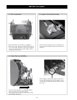
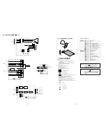
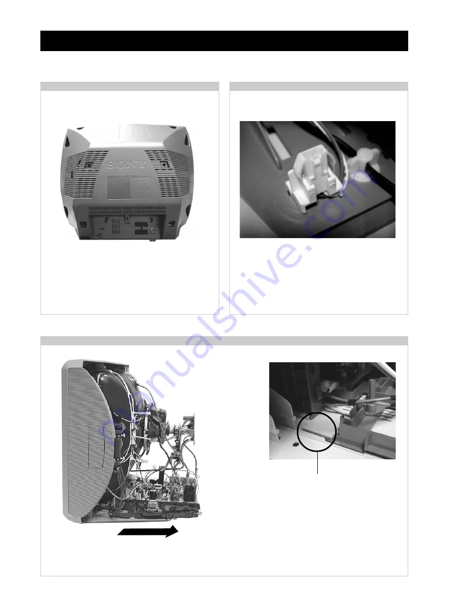
2-1. Rear Cover Removal

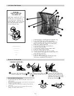
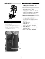
Release the mains power cable from its securing posts.
Remove the rear cover fixing screws indicated. Pull the rear
cover  away from the front beznet. Take care when removing
the rear cover not to damage the speaker cables as speakers
are fitted inside the rear cover.

2-2. Speaker Connector Disconnection

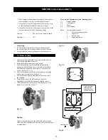
Before completely removing the rear cover disconnect the
speaker connectors which are located on the inside base of
the beznet.

2-3. Chassis Removal and Refitting

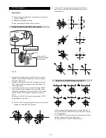
To remove lift the main bracket rear slightly and slide the
chassis  away from the beznet. Ensure that the
interconnecting leads are released from their purse locks to
prevent damage being caused.

When refitting the chassis ensure that the main bracket is
located in the beznet guide slots before sliding the chassis
forwards. Refit the interconnecting leads in their respective
purse locks.

Summary of Contents for FD Trinitron KV-29LS30K

Page 1: ...IS NO KV 29LS30E RM 887 ESP SCC Q53F A KV 29LS30K RM 887 OIRT SCC Q51G A KV 29LS30U RM 887 UK SCC Q52F A MODEL COMMANDER DEST CHASSIS NO RM 889 KV 29LS35B RM 932 FR SCC Q54F G KV 29LS35E RM 932 ESP SCC Q53G A KV 29LS35K RM 932 OIRT SCC Q51H A RM 887 RM 932 ...

Page 2: ...ON THE CRT AFTER REMOVAL OF THE ANODE CAP WARNING AN ISOLATION TRANSFORMER SHOULD BE USED DURING ANY SERVICE WORK TO AVOID POSSIBLE SHOCK HAZARD DUE TO LIVE CHASSIS THE CHASSIS OF THIS RECEIVER IS DIRECTLY CONNECTED TO THE POWER LINE SAFETY RELATED COMPONENT WARNING COMPONENTS IDENTIFIED BY SHADING AND MARKED ON THE SCHEMATIC DIAGRAMS EXPLODED VIEWS AND IN THE PARTS LIST ARE CRITICAL FOR SAFE OPER...

Page 3: ...o r u E n i p 1 2 1 d r a d n a t s C E L E N E C s l a n g i s o e d i V d n a o i d u A r o f s t u p n I B G R r o f s t u p n I o i d u A d n a o e d i V V T f o s t u p t u O s l a n g i s s t n e m e r i u q e R r e w o P V 0 4 2 0 2 2 n o i t p m u s n o C r e w o P W 4 9 r o t c e n n o c o r u E n i p 1 2 2 s l a n g i s o e d i V d n a o i d u A r o f s t u p n I o e d i V S r o f s t u ...

Page 4: ...e and replace the fuse FUSE e m a N l e d o M m e t I E 0 3 S L 9 2 V K K 0 3 S L 9 2 V K U 0 3 S L 9 2 V K B 5 3 S L 9 2 V K E 5 3 S L 9 2 V K K 5 3 S L 9 2 V K b m o C l a P F F O F F O F F O F F O F F O F F O P I P F F O F F O F F O F F O F F O F F O y t i r o i r P B G R N O N O N O N O N O N O x o B r e f o o W N O N O N O N O N O N O 1 t r a c S N O N O N O N O N O N O 2 t r a c S N O N O N ...

Page 5: ... Open 13 Ground red 14 Ground blanking 15 _ _ Red input 0 7 3dB 75 ohms positive _ S signal Chroma input 0 3 3dB 75 ohms positive 16 Blanking input Ys signal High state 1 3V Low state 0 0 4V Input impedence 75 ohms 17 Ground video output 18 Ground video input 19 Video output 1V 3dB 75ohms positive sync 0 3V 3 10dB 20 _ _ Video input 1V 3dB 75ohms positive sync 0 3V 3 10dB _ Video input Y S signal ...

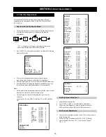
Page 6: ...ng sequence of buttons on the Remote Commander i 5 ON SCREEN DIGIT 5 VOLUME TV DISPLAY 3 The following table will be displayed indicating the error count Table 2 Note To clear the error count data press 80 on the Remote commander U N E M R O R R E 2 0 E 3 0 E 4 0 E 5 0 E 6 0 E 7 0 E 8 0 E 9 0 E 0 1 E 1 1 E E M I T G N I K R O W S R U O H S E T U N I M P C O A N P V O C N Y S V R K I C I I M V N E ...

Page 7: ... Adjust now then press OK and correct any slant of the picture between 5 and 5 by pressing or Finally press OK to store 8 First Time Operation Your TV is now ready for use 5 The Auto Tuning menu appears on the screen Press the OK button to select Yes 6 The TV starts to automatically search and store all available channels TV Broadcast for you This procedure could take some minutes Please be patien...

Page 8: ...selecting the option press then press or to set the time period delay max of 4 hours and finally press OK to store While watching the TV you can press the button on the remote control to display the time remaining One minute before the TV switches itself into standby mode the time remaining is displayed on the TV screen automatically LANGUAGE COUNTRY The Language Country option in the Set Up menu ...

Page 9: ...e To operate teletext use the remote control buttons as indicated below Make sure to use a channel TV Broadcast with a strong signal otherwise teletext errors may occur To Switch On Teletext After select the channel TV Broadcast which carries the teletext you wish to view press To Select a Teletext page Input 3 digits for the page number using the numbered buttons If you have made a mistake retype...

Page 10: ...A B C 1 2 PlayStation Decoder VCR VCR Decoder Hi fi E D VCR DVD F PlayStation is a product of Sony Computer Entertainment Inc PlayStation is a trademark of Sony Computer Entertainment Inc 8mm Hi8 DVC camcorder 20 Specifications 29LS30 Additional Information TV system B G H D K Colour system PAL SECAM NTSC 3 58 4 43 only Video In Channel Coverage VHF E2 E12 UHF E21 E69 CATV S1 S20 HYPER S21 S41 D K...

Page 11: ... system select the Picture Rotation option in the Detail Set Up menu to correct the picture slant Using the menu system select the Manual Programme Preset menu and adjust Fine Tuning AFT to obtain better picture reception Using the menu system select the Noise Reduction option in the Detail Set Up menu and select On to reduce the noise in the picture Using the menu system select the Set Up menu Th...

Page 12: ...n Before completely removing the rear cover disconnect the speaker connectors which are located on the inside base of thebeznet 2 3 Chassis Removal and Refitting To remove lift the main bracket rear slightly and slide the chassis away from the beznet Ensure that the interconnecting leads are released from their purse locks to prevent damage being caused When refitting the chassis ensure that the m...

Page 13: ...t servicing Remove the two screws fixing the user control module to the side of the set The control module can then be removed by sliding it towards the rear of the set allowing access to the H2 Board Screws Remove the screw securing the PWB to the main bracket Clip 2 5 A Board PWB Removal Step 2 2 4 A Board PWB Removal Step 1 2 7 Side Control Module Removal 2 6 Service Position ...

Page 14: ... Anode Cap 2 8 Picture Tube Removal WARNING BEFORE REMOVING THE ANODE CAP High voltage remains in the CRT even after the power is disconnected To avoid electric shock discharge CRT before attempting to remove the anode cap Short between anode and CRT coated earth ground strap Coated Earth Ground Strap 1 Discharge the anode of the CRT and remove the anode cap 2 Release the EHT lead from its CRT sup...

Page 15: ... Green and verify the condition 6 When the position of the deflection yoke has been determined fasten the deflection yoke with the screws 7 If the beam does not land correctly in all the corners use a magnet to correct it See Fig 3 4 When complete readjustment is necessary or a new picture tube is installed carry out the following adjustments Unless there are specific instructions to the contrary ...

Page 16: ...e each other The movement of the magnets interact with each other and so the respective dot position should be monitored while carrying out this adjustment Use the H STAT VR to adjust the Red Green and Blue dots so that they coincide at the centre of the screen by moving the dots in the horizontal direction G B R G B R G B R G B R G B R G B R 3 2 Convergence Operation of the BMC Hexapole magnet Pr...

Page 17: ...rtical static convergence 1 Remove the deflection yoke spacer 2 Tilt the deflection yoke as indicated in the figure below and optimise the geometry Tilting the DY Up and Down will balance the upper and lower pin adjustment Tilting the DY Left and Right will balance the H Trap adjustment 3 Re install the deflection yoke spacer Screen Corner Convergence TLH pieces Deflection Yoke a b d Permalloy Ass...

Page 18: ...back Transformer to the point where the OSD menu indication shows OK Layout of each control 1 Input an all white signal from the pattern generator 2 Enter into the Service Mode by pressing TEST TEST and MENU on the Service Commander 3 Select Service from the on screen menu display and press the right arrow button on the remote commander 4 The Service menu will appear on the screen See Page 19 5 Se...

Page 19: ...Mode T S U J D A F I t s u j d A C G A e t u m o t u A n i a G o i d u A g n i t a G L 5 1 6 1 0 1 0 0 y r t e m o e G e c i v r e S n g i s e D s u t a t S d n u o S t s u j d a F I u n e M r o r r E 0 3 1 v o e r e t S 2 E F h F F h F F a t a d y r o t c a F G 1 1 4 3 P S M e c i v e D P S M E C I V R E S R t e s f f O G t e s f f O e v i r D R e v i r D G e v i r D B q e r F k a e P y a l e D a...

Page 20: ...oltage is 3 5volts 0 3volts 4 If adjustment is required then re adjust theAGC variable resistor located at the top rear of the FRONTEND to obtain a voltage of 3 5V 0 3V 1 Enter into the Geometry service menu 2 Select and adjust each item in order to obtain the optimum image Print side of A board Deflection System Adjustment V SIZE V LIN S CORRECTION V CENTRE H CENTRE H SIZE PIN AMP PIN PHASE CORNE...

Page 21: ... a s s e n t h g i r B b u S 4 1 t n e m t s u j d a n o i t i s o P H t x e T 5 1 t s e T l i o C n o i t a t o R 6 1 0 5 l e v e l e r u t c i P 9 1 e l b a s i D e l b a n E e d o M y r o t c a F 1 2 R K E D A n o i t a n i t s e D 2 2 L B n o i t a n i t s e D 3 2 R K E D A n o i t a n i t s e D 4 2 U n o i t a n i t s e D 5 2 R K E D A n o i t a n i t s e D 6 2 L B n o i t a n i t s e D 7 2 R...

Page 22: ...22 Memo ...

Page 23: ...C QCP DETECT Q612 602 1 4 CN1201 J1200 R AUDIO 64 XTAL IN 40 AUDIO MUTE 5 AUD OUT 78 3 3V STBY 6 5 2 3 7 1 5V STBY IC201 AUDIO AMP MUTE 1 IN INL 10 3 OUT W H DRIVE Q535 68 IC401 AV LINK 5V STBY 69 R0 56 A10 B10 1 2 3 6 G0 57 B0 58 IK 55 GREEN BLUE IK EWD 17 VD 18 VD 19 ABL 54 74 TO C BOARD CN703 TO C BOARD CN1705 7 CN504 J401 2 2 NSC CORRECT ROT COIL AGC SCL SDA VIDEO IC004 SDA 6 SCL 5 7 WP 71 SCL...

Page 24: ...RATURE ALR HIGH RIPPLE Les composants identifiés par une trame et par une marque sont d une importance critique pour la sécurité Ne les remplacer que par des pièces de numéro spécifié specified Note The components identified by shading and marked are critical for safety Replace only with the part numbers specified in the parts list Note CVM Board A Board S1 Board VM C H D1 A J A2 N D A1 D2 C A VM ...

Page 25: ...Vp p H TP5 20us div 74 Vp p H TP6 20us div 1 76 Vp p H TP7 10us div 1 77 Vp p H TP1 20us div TP4 74 Vp p H TP4 C BoardWaveforms o N f e R o N n i P V e g a t l o V o N f e R o N n i P V e g a t l o V 1 0 7 1 C I 1 1 3 1 0 8 1 C I 1 3 1 2 1 2 2 3 1 3 0 3 3 4 1 5 5 5 5 1 4 7 1 3 1 6 1 4 8 3 2 1 7 0 7 9 6 4 2 1 8 0 8 ...

Page 26: ...29 30 VM VELOCITY MODULATION ...

Page 27: ...31 32 F2 AC FILTER FUSE SIRCS H2 AV3 INPUT ...

Page 28: ...D 3 D 1 1 4 D 3 C 4 2 4 D 2 M 5 0 5 D 2 M 8 3 5 D 6 E 2 1 6 D 5 G 5 2 6 D 6 H R O T S I S N A R T 2 3 5 Q 4 D 9 0 6 Q 6 J 4 0 0 C I 2 H 1 0 0 D 2 I 6 1 0 D 2 J 4 0 1 D 2 E 9 3 2 D 3 D 2 1 4 D 3 D 7 2 4 D 4 A 6 0 5 D 4 D 9 3 5 D 5 B 3 1 6 D 6 J 7 2 6 D 7 K 3 1 0 Q 3 I 3 3 5 Q 6 A 0 1 2 1 Q 3 H 1 0 4 C I 3 I 2 0 0 D 3 I 8 1 0 D 3 I 5 0 1 D 1 A 2 0 4 D 3 E 3 1 4 D 3 C 8 2 4 D 3 C 7 0 5 D 2 M 1 4 5 D ...

Page 29: ...35 36 37 KV 29LS30 35 9 927 403 01 A POWER SUPPLY DEFLECTION AUDIO AMPLIFIER Page 1 2 ...

Page 30: ...rms 1 83 Vp p V 20us div TP7 20us div 1 88 Vp p H TP1 5ms div TP8 488 mVp p V 20us div 1 86 Vp p H TP3 20us div 1 84 Vp p H TP2 20us div 6 0 Vp p H TP4 20us div 5 4 Vp p H TP5 20us div TP6 16 8 Vp p H 5ms div 50 8 Vp p V TP11 5ms div 49 8 Vp p V TP9 20us div TP10 1 06 kVp p H ...

Page 31: ...SC2785 HFE 2SA933AS QRT 2SAG33ASQT 2SA933AS RT 2SC1740S RT IRF614 LF DAN202K DAN202K T146 D4SB60L F AK04 V1 AU 01Z V1 BYD33G BYD33G AMMO DINL20 U TA2 DINL40 U TR2 ERB44 06TP1 EGP20G EG 1Z V1 EL1Z ERD28 06S ERD28 06S ERC06 15SL FMN G12S GP08DPKG23 RGP10GPKG23 RG1CLF B1 RU 3AM RU3YX LF C4 RU3YX V1 RU 4AM T3 1SS292T 77 8 7 6 5 1 3 4 TOP VIEW 2 1 2 3 1 V OUT 2 V IN 3 GND TOP VIEW E C B C B E B C E B C...

Page 32: ...ZJ T 77 9 1B MTZJ T 77 10 MTZJ T 77 10A MTZJ T 77 10B MTZJ T 77 15B MTZJ T 77 33A MTZJ 33C MTZJ 7 5B P6KE200ASY RD3 9ES B2 RD7 5ESB2 RD9 1ES B3 RD10ESB2 RD15ES T1B2 1SS119 25TD 1SS133T 77 1SS355TE 17 RD12SB2 UDZS TE 17 4 7B UDZS TE 17 5 6B UDZS TE 17 6 8B UDZS TE 17 9 1B UDZ TE 17 22B UF4005PKG23 CATHODE ANODE CATHODE ANODE CATHODE ANODE CATHODE ANODE 1 32 33 64 MSP3410D MSP3411D ...

Page 33: ...Latch Centre Osc SS F B Timer TSD OCP Control Logic Level Shift Sel 34v ref 5v 15v 8v Driver Reg 10v 18 8 14 16 15 10 12 11 9 A BOARD IC604 BA41W12ST V5 A BOARD IC401 IC531 LM393DT A BOARD IC601 MCZ3001D A BOARD IC1201 TDA7497 9 8 11 5 Pwr Gnd MUTE STBY PROTECTION 14 7 Sgn Gnd 1 10 60K 12 15 13 Pwr Gnd Vss ...

Page 34: ... 776 204 12 POWER CORD FILTER KV 29LS35B 6 4 206 048 01 BRACKET MAIN 7 1 424 733 11 COIL PFC CHOKE 65MMH 8 1 453 308 31 TRANSFORMER ASSY FLYBACK NX 4521 Z2B4 9 8 598 533 00 FRONTEND BTF EC411 KV 29LS30E 29LS30K KV 29LS35E 29LS35K 8 598 529 00 FRONTEND BTF EU611 KV 29LS30U 8 598 535 10 FRONTEND BTF EF411 KV 29LS35B 10 A 1632 925 A A BOARD COMPLETE KV 29LS30E 29LS30K A 1632 933 A A BOARD COMPLETE KV...

Page 35: ...59 4 205 950 01 CRT SUPPORTER 60 8 735 053 05 PICTURE TUBE M68LNH060X 61 8 451 494 51 DEFLECTION YOKE Y29RSA L 62 1 452 896 11 COIL NA ROTATION RT 200 63 A 1645 045 A VM BOARD COMPLETE 64 A 1639 019 A C BOARD COMPLETE 65 4 369 318 22 SPRING TENSION 66 1 416 654 11 COIL DEMAGNETIC 67 4 203 390 11 CUSHION DGC 68 4 204 768 01 HOLDER DGC 69 8 453 011 11 NECK ASSY NA299 M 70 1 251 537 22 CAP ASSY HIGH ...

Page 36: ...odel and therefore do not appear in the Parts List 46 F2 BOARD COMPLETE Parts List 47 A BOARD COMMON Parts List Parts common to all models listed in this manual 47 A BOARD VARIANT Parts List Parts that belong only to the model specified Model KV 29LS30 55 KV 29LS35 55 C BOARD COMPLETE Parts List 55 VM BOARD COMPLETE Parts List 55 H2 BOARD COMPLETE Parts List 57 MISCELLANEOUS 58 ACCESSORIES AND PAC...

Page 37: ...CT 470UF 20 00 16V C053 1 164 004 91 CERAMIC CHIP 0 1UF 10 00 25V C055 1 126 960 91 ELECT 1UF 20 00 50V C100 1 126 933 91 ELECT 100UF 20 00 16V C103 1 126 965 91 ELECT 22UF 20 00 50V C105 1 162 970 91 CERAMIC CHIP 0 01UF 10 00 25V C106 1 126 933 91 ELECT 100UF 20 00 16V C112 1 162 970 91 CERAMIC CHIP 0 01UF 10 00 25V C204 1 115 340 91 CERAMIC CHIP 0 22UF 10 00 25V C211 1 162 970 91 CERAMIC CHIP 0 ...

Page 38: ... CHIP 1UF 16V C438 1 164 346 91 CERAMIC CHIP 1UF 16V C445 1 126 964 91 ELECT 10UF 20 00 50V C446 1 126 964 91 ELECT 10UF 20 00 50V C447 1 162 970 91 CERAMIC CHIP 0 01UF 10 00 25V C449 1 127 715 91 CERAMIC CHIP 0 22UF 10 16V C501 1 126 968 91 ELECT 100UF 20 00 50V C502 1 163 038 91 CERAMIC CHIP 0 1UF 25V C503 1 111 116 91 ELECT 100UF 20 00 50V C504 1 106 220 91 MYLAR 0 1UF 10 00 100V C505 1 137 194...

Page 39: ...0 50V C610 1 126 941 91 ELECT 470UF 20 00 25V C611 1 163 009 91 CERAMIC CHIP 0 001UF 10 00 50V C612 1 104 571 91 CERAMIC 0 0015UF 10 00 2KV C613 1 104 571 91 CERAMIC 0 0015UF 10 00 2KV C614 1 161 964 51 CERAMIC 0 0047UF 250V C615 1 115 339 91 CERAMIC CHIP 0 1UF 10 00 50V C616 1 165 127 91 CERAMIC 470PF 10 00 500V C617 1 165 127 91 CERAMIC 470PF 10 00 500V C618 1 126 949 91 ELECT 220UF 20 00 35V C6...

Page 40: ...A D101 8 719 977 81 DIODE DTZ33B D103 8 719 081 98 DIODE MM3Z6V8T1 D104 8 719 069 55 DIODE UDZSTE 175 6B D105 8 719 069 55 DIODE UDZSTE 175 6B D106 8 719 069 55 DIODE UDZSTE 175 6B D107 8 719 069 55 DIODE UDZSTE 175 6B D207 8 719 069 57 DIODE UDZS T2 6 8B D210 8 719 069 55 DIODE UDZSTE 175 6B D211 8 719 069 60 DIODE UDZSTE 179 1B D212 8 719 914 43 DIODE DAN202K D228 8 719 069 55 DIODE UDZSTE 175 6...

Page 41: ...41 INDUCTOR 3 3MH L533 1 406 989 11 INDUCTOR 10MH L534 1 216 025 91 RES CHIP 100 5 1 10W L535 1 459 111 21 INDUCTOR 10MH L601 1 408 603 21 INDUCTOR 10UH L602 1 408 611 21 INDUCTOR 47UH L603 1 535 143 61 LEAD JUMPER 5 0MM L1200 1 535 143 61 LEAD JUMPER 5 0MM L1201 1 535 143 61 LEAD JUMPER 5 0MM L1203 1 535 143 61 LEAD JUMPER 5 0MM PHOTO COUPLER PH601 8 749 016 21 IC TCET1103G IC LINK PS1201 1 535 1...

Page 42: ...100 5 1 10W R246 1 260 107 91 CARBON 4 7K 5 1 2W R248 1 249 429 91 CARBON 10K 5 1 4W R249 1 216 097 91 RES CHIP 100K 5 1 10W R250 1 216 230 91 RES CHIP 22K 5 1 8W R251 1 216 069 91 RES CHIP 6 8K 5 1 10W A JR21 1 216 295 91 SHORT 0 JR24 1 216 295 91 SHORT 0 JR25 1 216 295 91 SHORT 0 JR26 1 216 295 91 SHORT 0 JR101 1 216 295 91 SHORT 0 JR419 1 216 295 91 SHORT 0 JR423 1 216 296 91 SHORT 0 JR508 1 21...

Page 43: ... 1 10W R544 1 216 103 91 RES CHIP 180K 5 1 10W R546 1 215 479 51 METAL OXIDE 560 5 3W R547 1 535 143 71 LEAD JUMPER 7 5MM R548 1 249 387 91 CARBON 3 3 5 1 4W A R252 1 216 069 91 RES CHIP 6 8K 5 1 10W R253 1 216 025 91 RES CHIP 100 5 1 10W R254 1 216 025 91 RES CHIP 100 5 1 10W R401 1 410 993 42 INDUCTOR 1UH R402 1 216 041 91 RES CHIP 470 5 1 10W R403 1 216 113 91 RES CHIP 470K 5 1 10W R404 1 216 1...

Page 44: ...ETAL 330K 1 1 4W R634 1 217 625 11 METAL 0 05 10 2W R635 1 260 300 71 CARBON 4 7 5 1 2W R636 1 249 413 91 CARBON 470 5 1 4W R637 1 216 041 91 RES CHIP 470 5 1 10W R639 1 208 814 91 METAL CHIP 22K 0 5 1 10W R640 1 208 830 91 METAL CHIP 100K 0 5 1 10W A R641 1 216 097 91 RES CHIP 100K 5 1 10W R642 1 249 405 91 CARBON 100 5 1 4W R643 1 216 089 91 RES CHIP 47K 5 1 10W R645 1 216 073 91 RES CHIP 10K 5 ...

Page 45: ...GP10GPG23 D706 8 719 901 83 DIODE 1SS83 D707 8 719 901 83 DIODE 1SS83 A D708 8 719 923 46 DIODE MTZJ T 77 6 8B D709 8 719 923 46 DIODE MTZJ T 77 6 8B D710 8 719 923 46 DIODE MTZJ T 77 6 8B D1801 8 719 048 53 DIODE MTZJ T 77 10 D1802 8 719 048 53 DIODE MTZJ T 77 10 D1803 8 719 048 53 DIODE MTZJ T 77 10 IC IC701 8 759 562 43 IC TDA6108JF N1B IC1801 8 759 603 37 IC M5216P SOCKET J701 1 251 732 11 SOC...

Page 46: ...UF 10 00 250V C1711 1 106 375 81 MYLAR 0 022UF 10 00 250V C1713 1 110 182 81 FILM 0 022UF 10 00 250V C1721 1 107 639 91 ELECT 47UF 20 00 160V C1722 1 136 153 81 FILM 0 01UF 5 00 50V C1723 1 126 935 91 ELECT 470UF 20 00 10V C1728 1 126 935 91 ELECT 470UF 20 00 10V C1733 1 104 664 91 ELECT 47UF 20 00 25V C1734 1 104 664 91 ELECT 47UF 20 00 25V C1737 1 104 999 51 FILM 0 01UF 5 00 200V C1844 1 129 716...

Page 47: ...215 922 91 METAL OXIDE 6 8K 5 3W R1919 1 216 675 91 METAL CHIP 10K 0 5 1 10W R1920 1 216 295 91 SHORT 0 R1921 1 215 922 91 METAL OXIDE 6 8K 5 3W R1922 1 215 919 91 METAL OXIDE 2 2K 5 3W R1923 1 216 097 91 RES CHIP 100K 5 1 10W R1924 1 216 097 91 RES CHIP 100K 5 1 10W R1925 1 216 097 91 RES CHIP 100K 5 1 10W R1926 1 216 295 91 SHORT 0 R1931 1 216 691 91 METAL CHIP 47K 0 5 1 10W R1953 1 216 107 91 R...

Page 48: ...1 91 CARBON 15K 5 1 4W R915 1 249 406 91 CARBON 120 5 1 4W R916 1 249 406 91 CARBON 120 5 1 4W R917 1 247 807 91 CARBON 100 5 1 4W R918 1 247 807 91 CARBON 100 5 1 4W SWITCH S900 1 692 979 11 SWITCH TACTILE S901 1 692 979 11 SWITCH TACTILE S902 1 692 979 11 SWITCH TACTILE MISCELLANEOUS 1 416 654 11 COIL DEMAGNETIC 1 452 032 11 MAGNET DISK 10MM 1 452 094 00 MAGNET ROTATABLE DISK 15MM 1 452 896 11 C...

Page 49: ...e modules Please contact your local Sony Service organisation for the latest information Read restore and compare NVM contents via the I2C bus Acknowledge check of all I2C devices in the TV set Read Error Codes emulation of the Error Reader tool Remote Commander emulation User programmable Functional Check through Infrared Fast and documented Test Mode setting of all Sony TV chassis Partnumbers TR...

Reviews: