iii
Over Current Protection (OCP)
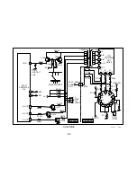
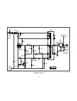
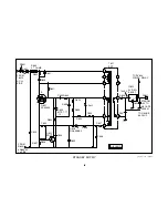
Monitoring the voltage across R637 is used for over current protection.
This voltage is representative of the amount of current flowing through
Q621 Converter since it is in series with the transistor. If this voltage
should rise to .6 volts, it will cause Q622 to turn ON. If Q622 were to turn
ON, it would shunt Q621/G voltage to ground. This would cause Q621
Converter to stop conducting.
Over Voltage Protection (OVP)
Over voltage protection is done by rectifying the voltage at T621/6 with
D627. This voltage is filtered by C636 and applied to D626 through R638.
If this voltage should rise above 6.2 volts, D626 begins to conduct. When
its conduction allows Q622 Protect to turn ON, over voltage protection is
employed. Q622 Protect turns ON and grounds Q621/G, which stops the
converter from switching.
D699 is also used for OVP. The signal from T621/4 is rectified by D698.
This creates a negative voltage across C699. If this negative voltage
becomes great enough, D699 conducts and the Q621/G voltage is brought
lower.
Secondary Output
The power coupled through T621 SRT places a voltage on T621/9 that,
when rectified and filtered by D628 and C637, is 7.2 volts. This voltage is
constant due to the regulation circuit on the primary side of T621 SRT.
This 7.2 volts is applied to Q646/E for backup during the start of regula-
tion by the regular power supply.
It is also applied to IC622 5-Volt Regulator, which regulates its output to 5
volts. This 5 volts is sent to CN641/10 which connects to the A board and
powers the Tuning Micon and other circuits. It is also applied to RY600
Power Relay.
Checking Q621
Testing a MOSFET device is simple. The leads show infinite resistance
to each other except for drain to source in one direction because of the
presence of a protection diode.
To prove the device is functional:
1. Connect the negative lead of the ohmmeter to the SOURCE lead.
2. Touch the ohmmeter positive lead to the gate, to pre-charge it.
3. Connect the ohmmeter positive lead to the DRAIN. If the device is
good you will get a resistance reading of about 400-1k ohms.
Some DVMs do not produce enough DC voltage in the ohms mode. The
diode check mode can be used with these models. When using the diode
mode, a low voltage drop is shown after pre-charging the gate.
Summary of Contents for FD TRINITRON WEGA KV-13FM12
Page 27: ...22 NOTES ...
Page 48: ...APPENDIX ...

