background image

8

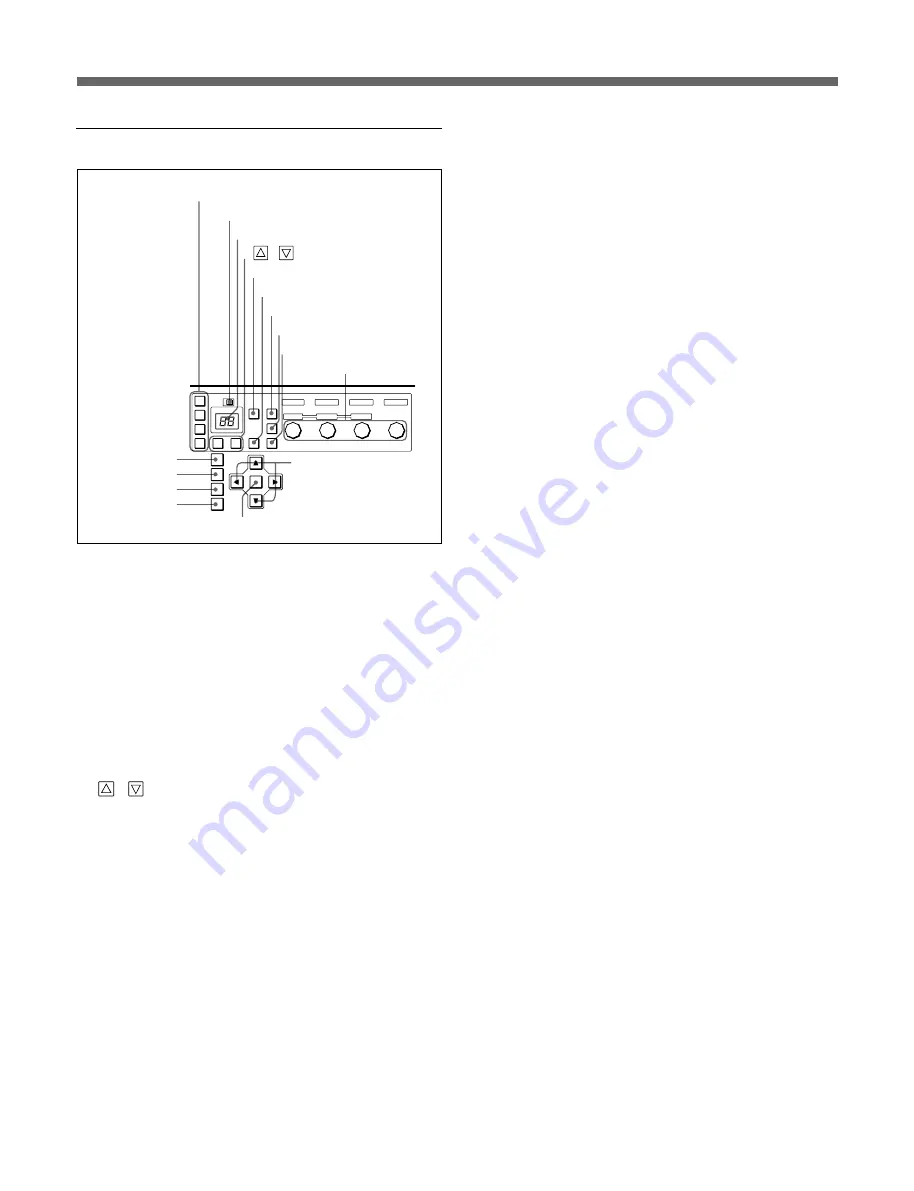
Menu operation block

1

Output select buttons

Select a video output channel during menu operation.

2

KEY INHIBIT switch

OFF: Activates all the buttons on the control panel.
ON: Deactivates all the buttons on the control panel.

3

MODE display window

Shows the selected mode number in hexadecimal
notation.

4

 / 

 buttons

Selects the mode number displayed in the mode
display window.

5

MODE button

Selects the mode or the setting during mode operation.
The selected mode number is displayed in the MODE
display window.

6

FUNCTION button

Activates the extended functions of the MEMORY and
EXECUTE buttons.

7

MEMORY button

Activates the memory function.

8

SOURCE button

Selects the input video signal source.

9

EXECUTE button

Executes the function selected with the control knobs

and MODE button.

0

Control knobs

Adjusts the picture-quality component selected with

the MODE button.

qa

MENU button

Enters a menu mode.

qs

HOME button

Returns to the home menu.

qd

CMD1 button

Activates command function 1.

qf

CMD2 button

Activates command function 2.

qg

Set button

Registers the selections in a menu operation.

qh

Cursor buttons

Select a menu item and its setting.

KEY INHIBIT

1

2

3

4

MODE

MODE

MEMORY

MASTER

PAN

IRIS

RED

TILT

FOCUS

GREEN

ZOOM

ZOOM

BLUE

f

F

ROTATION

SOURCE

EXECUTE

FUNCTION

ON

OFF

MENU

HOME

CMD1

CMD2

qh

Cursor buttons

1

Output select buttons

2

KEY INHIBIT switch

3

MODE display window

4

 / 

 buttons

5

MODE button

6

FUNCTION button

7

MEMORY button

8

SOURCE button

9

EXECUTE button

0

Control knobs

qa

MENU button

qs

HOME button

qg

Set button

qf

CMD2 button

Locations and Functions of Parts

qd

CMD1 button

Summary of Contents for FVS-1000 Series

Page 1: ...OPERATION MANUAL English 1st Edition Revised 4 MULTI RESOLUTION FILM SCANNER FVS 1000 series ...

Page 2: ...r un technicien agrée Sony ACHTUNG Die Installation darf nur von autorisiertem Sony Fachpersonal ausgeführt werden For the customers in the USA This equipment has been tested and found to comply with the limits for a Class A digital device pursuant to Part 15 of the FCC Rules These limits are designed to provide reasonable protection against harmful interference when the equipment is operated in a...

Page 3: ...Connector Panel 10 Film Loading 15 Changing the lens 15 Loading the film 19 Operations 20 Playback 20 Stopping the System Temporarily 22 Controlling the Unit With an External Device 22 Menu Operations 23 Basic Operations 23 Mode Operations 24 Checking an Input Signal 25 Loading and Storing Data 25 Menu Items 26 Specifications 37 ...

Page 4: ...me base corrector assures stable audio reproduction even if film transport is unstable Reproduced audio signals are output coinciding with video signal output by using a built in audio delay circuit with sufficient margin Primary color correction Area array CCD technology allows the FVS 1000 to integrate a powerful primary color correction system comprising digital light control logarithmic signal...

Page 5: ...NDBY button 2 HALT button 3 Power switch Control panel See page 6 Signal processing block Notes If a front or rear door is open an interlock switch will be set to OFF and power is not supplied to the film transport block even if the power switch is set to I These switches do not turn ON or OFF the power to the optional devices installed in the unit To control the power supply to the installed devi...

Page 6: ...ations and Functions of Parts Connector panel See page 10 3 Remote connector panel 4 AC inlet for this unit 5 AC inlet for optional devices 1 Interlock switch 2 LENS EXCHANGE button 1 Interlock switch Detects whether the rear door is open or closed If you open the door power supply to the film transport block is disabled 2 LENS EXCHANGE button Press to exchange the lens The button starts flashing ...

Page 7: ...the lamp on 1 Interlock switches Detect whether the front doors are open or closed If you open a door power supply to the film transport block is disabled 2 Supply reel Mount the film 3 Take up reel Attach a reel for winding the film 4 Film stoppers Turn these rods over the film to avoid loosening of the roll 2 Supply reel 1 Interlock switches 3 Take up reel 6 PT rollers 4 Film stoppers 5 Film dir...

Page 8: ...PE REVERSE MENU HOME CMD1 CMD2 field MODE FORWARD Indicator block See below Display block See page 7 Menu operation block See page 8 Film operation block See page 9 1REMOTE button 2READY button Locations and Functions of Parts 2 FILM RATE indicators Show the film rate setting 23 976 24 24 975 25 29 97 or 30 3 REFERENCE indicators Show the reference video signal settings 1125 for HD TV system 30 24...

Page 9: ...ach the SOURCE and DESTINATION display windows shows the code that indicates the data displayed in the window 9 PRESET button1 Presets the data shown in the SOURCE and DESTINATION display windows 0 RESET button Resets the data shown in the SOURCE and DESTINATION display windows qa Menu display window Menus selected with the buttons in the menu operation block appear here qs Mode display block Sett...

Page 10: ...XECUTE button Executes the function selected with the control knobs and MODE button 0 Control knobs Adjusts the picture quality component selected with the MODE button qa MENU button Enters a menu mode qs HOME button Returns to the home menu qd CMD1 button Activates command function 1 qf CMD2 button Activates command function 2 qg Set button Registers the selections in a menu operation qh Cursor b...

Page 11: ...o the rotational speed of the jog shuttle dial In this mode the dial does not click 9 VAR button Press to select variable speed playback mode in a maximum range of 2 to 2 times normal playback speed In this mode this button lights and the jog shuttle dial clicks at the positions for still picture and 1 time normal playback speed 0 Jog shuttle dial Rotate to search for a desired point Rotate the di...

Page 12: ...HD OUT 1 2 1 LINK B 2 3 1 MONITOR SUPER 2 3 TC SQ 3 LINK A MONI OUT HD IN LINK B MONI OUT REF LINK A LOG OUT AUDIO 1 2 1 LINK B 2 3 TC 3 HD 30 IN OUT ON OFF ON OFF ON OFF ON OFF ON OFF ON OFF HD 25 IN OUT HD 24 IN OUT 525 IN OUT 625 50 IN OUT 625 48 TERMINATE IN OUT RS 232C AUX SD OUT board SD IN board BKFV 200 boards BKFV 100 boards REF board Locations and Functions of Parts BKFV 300 board BKFV 5...

Page 13: ... the video monitors 4 TC connector BNC type Supplies a time code signal This function is not available now 5 SQ connector BNC type Supplies a sequential signal SD IN board 1 LINK A B C connectors BNC type Accept the SD signals selected from the menu BKFV 200 boards optional These boards are the same as the SD OUT board and the SD IN board originally provided with the system LINK SD OUT A B 1 D 1 S...

Page 14: ... BNC type Accepts the HD A signal selected from the menu 7 MONI OUT monitor output connector BNC type Supplies the signal input to the LINK A connector for monitoring 8 LINK B connector BNC type Accepts the HD B signal selected from the menu 9 MONI OUT monitor output connector BNC type Supplies the signal input to the LINK B connector for monitoring Locations and Functions of Parts HD OUT board LI...

Page 15: ... with the audio head block 2 ANALOG OUT analog audio output connector D sub 15 pin Supplies analog audio signals of line level Two pairs of left and right audio signals A and B are output Connect to an analog mixing console analog amplifier etc using the supplied D sub 15 pin XLR 3 pin conversion cable 3 DIGITAL OUT digital audio output connector D sub 9 pin Supplies digital audio signals of line ...

Page 16: ... for the 625 50 TV system to the IN connector The OUT connector supplies the signal input to the IN connector when the termination switch is set to OFF and the reference signal generated internally when the switch is set to ON 6 625 48 IN OUT connectors BNC type Input a reference signal for the 625 48 TV system to the IN connector The OUT connector supplies the signal input to the IN connector whe...

Page 17: ...NGE button The button starts flashing then lights after a few seconds 2 When the button lights open the rear door 3 Pull up the two lock levers to release the lock 4 Pull out the camera block 5 Disconnect the lens connector on the camera block 6 Turn the lens mount lever in the direction of the arrow then remove the lens LENS EXCHANGE button Camera block Lock levers Lens connector Lens Lens mount ...

Page 18: ...sure to turn off the power by setting the power switch to the a side 1 Remove the OPS cover by pulling it out 2 Loosen the two fixing screws by turning them counterclockwise 90 degrees 3 Remove the retainer assembly by pulling it out 4 Loosen the two fixing screws by turning them counterclockwise 90 degrees 5 Remove the gate assembly by pulling it out 6 Attach the new retainer assembly and gate as...

Page 19: ...ees 2 Remove the PAD assembly by pulling it out 3 Align the positioning pins and holes then attach the PAD assembly by pushing it in 4 Fasten the fixing screws by turning them clockwise To set the film stoppers Figures printed on the knob of the film stopper indicate film sizes Turn the knob 180 degrees so that the same figures as the film size to be used appear Be sure to set all four stoppers fo...

Page 20: ...ch the 35 mm core 16 mm film Attach the 16 mm core and core retainers as shown below then pull the film protector up Settings when the BKFV 500 is installed When the BKFV 500 is installed and audio signals are to be processed the switch must be set according to the film size as shown below 35 mm core 16 mm core Core retainers Film protector Film protector Switch ...

Page 21: ...e interlock switch is turned OFF with a door open wait at least 30 seconds before resetting the interlock switch 6 8 8 7 3 4 9 2 5 Directions of film transport Load the film following the instructions below 1 Open the front doors of the film mount table 2 Turn the center knobs counterclockwise until the black claws are pulled in 3 Mount the film onto the supply reel table Align the grooves of the ...

Page 22: ...the CMD2 button Manual air blow The machine send air to the film to blow off the dust from the film You can send air manually at any time by holding down the CMD2 and cursor center buttons simultaneously Electrostatic sensor adjustment The electrostatic sensor is automatically adjusted to the optimum level for each standby mode To adjust manually press the MARK IN button while holding down the CMD...

Page 23: ...esired shuttle playback speed then switch between normal speed playback and shuttle playback by pressing the PLAY and SHUTTLE buttons alternately Playback in variable mode In variable mode you can finely control the speed of playback in the range of 2 to 2 times normal speed There are click points on the search dial at the still position and at 1 time normal speed To carry out playback in variable...

Page 24: ...back speed is retrieved SD video output signals in VariPlay mode An optional BKFV 100 1 board must be installed An internal or external signal path must be set as follows with the menu on the control panel Internal signal path Set SIGNAL PATH on the SETUP menu to HD1 SD1 2a a External signal path Set SIGNAL PATH on the SETUP menu to HD1a a a aHD1IN SD1 2a a The same video rate must be set for both...

Page 25: ...of selectable items appears 5 To select an item Press the cursor or button to move the cursor or the cursor or button to select an item and press the Set cursor center button To adjust the level Turn the control knob corresponding to the item to be adjusted Repeat steps 2 to 5 as required To return to the HOME MENU If you press the HOME button with any menu displayed the HOME MENU page appears To ...

Page 26: ...the mode number For details on operations required for each mode are listed in the tables in Menu Items To set the data Operation 1 1 Select the mode number 2 Press the MODE button to select the setting 3 Press the EXECUTE button To control the level Operation 2 1 Select the mode number 2 Select a video output channel if necessary 3 Turn the control knobs To select a video output channel Operation...

Page 27: ...memory 1 Press the MEMORY button 2 Press the 1 2 3 or 4 button to select a video output channel 3 Press the or button to select the memory number 0 to 3 for HD and 0 to F for SD The image stored in the selected number is loaded To select a source Press the SOURCE button to select the source of the image to be stored For example 1 shows a main picture and 1 shows the external input To store the dat...

Page 28: ...or 5 inch core Char characteristics Select the film color characteristics NEGA Negative film PT PrimeTime I NEGA Inter negative IP Inter positive PRINT Print FILM RATE Select the film rate from among 24 25 and 30 For each film rate select 1 000 or 1 1 001 REFERENCE Ref reference Select a reference signal from among INTERNAL 1125 30 EXT 1125 24 EXT 1125 25 EXT 525 EXT or 625 50 EXT SIGNAL PATH SD1 ...

Page 29: ... 4 4 4 4 4 Y C 4 4 4 4 RGB 8 4 4H 8 4 4V 8 8 8 Y C a and 8 8 8 RGB a CHARACTER Control characters superimposed on the SD1 or SD2 signal ALL CHARA ON OFF MESSAGE ON OFF STATUS ON OFF FCT ON OFF TC ON OFF CHARA POSI H POSITION move in the horizontal direction V POSITION move in the vertical direction FORMATION change the order of STATUS FCT TC Set by turning three control knobs from the left CHARA T...

Page 30: ... a and 8 8 8 RGB a SYSTEM EXT DEVICE DLY Adjust the amount of delay of a video signal when it passes through an external device in SIGNAL PATH mode with the leftmost control knob HD INPUT Adjust the amount of delay of a video signal input to HD REMOTE LOCAL LOCAL ENA Restrict control from the local panel in remote mode ALL DISABLE Control from the local panel is inhibited in remote mode STOP Only ...

Page 31: ...n ND filter using the leftmost control knob Density filter 0 Clear 1 1 4 2 1 16 3 1 64 CC Color Select the CC filter using the second control knob from the left Conversion filter 0 Cross filter 1 3200K 2 4300K 3 6300K GAMMA VIDEO GAMMA Adjust the gamma of the linear domain R RED Adjust the video gamma of red G GREEN Adjust the video gamma of green B BLUE Adjust the video gamma of blue GAMMA CURVE ...

Page 32: ...l knobs V PEAK FREQ Adjust the effective range of the enhancer for the V peak frequency Select an output from among HD SD1 and SD2 LOW HIGH Adjust the point using the two leftmost control knobs H V MIX RATIO Adjust the ratio to add enhancement horizontally and vertically Select the output from among HD SD1 and SD2 Adjust the vertical ratio with the leftmost control knob DETAIL GAIN Adjust the deta...

Page 33: ...he flare R RED Adjust the flare of red G GREEN Adjust the flare of green B BLUE Adjust the flare of blue SHADING WHITE Adjust the shading BLACK Select BLACK Mode No 12 or WHITE Mode No 11 by pressing the cursor or button VSAW R RED Adjust the VSAW of red G GREEN Adjust the VSAW of green B BLUE Adjust the VSAW of blue VPARA R RED Adjust the VPARA of red G GREEN Adjust the VPARA of green B BLUE Adju...

Page 34: ...oom and Y Zoom source control Select an output from among HD SD1 and SD2 Select image framing from among Squeeze CROP and Letter Box Adjust panning using the leftmost control knob Adjust the X Zoom using the second control knob from the right Adjust the Y Zoom using the rightmost control knob TARGET Adjust the X Zoom and Y Zoom target control Select an output from among HD SD1 and SD2 Select image...

Page 35: ...LAY Set to ON for normal operations For internal adjustment set to OFF to disable the delay function EQUALIZER Set the use of an equalizer and its characteristics CUT To use a low cut filter and select a cut off frequency The adjustable range is from 8 0 kHz to 16 0 kHz 10 steps The characteristics for each cut off frequency are shown below OFF To not use any equalizer BOOST To use a slit loss com...

Page 36: ...ound picture SRC A and a foreground picture SRC B MAIN The main picture EXT A picture from external equipment MEM A picture stored in a memory bank INPUT CHECK Check an input signal For details on checking an input signal see Checking an Input Signal Select an output from among HD SD1 and SD2 and select an input signal OFF Normal EXT INPUT For checking an external input signal MEM For checking a s...

Page 37: ...OFTWARE VERSION The software version of the installed boards is shown TEST SIGNAL Select ON OFF of the test signal from the installed boards from the list below Select with the cursor buttons then press the SET button Board TSG IN side TSG OUT side ADC ON OFF MY ON OFF CC ON OFF ON OFF VE ON OFF EN ON 0FF IPM1 ON OFF DHP1 ON OFF OPM1 ON OFF DCP1 ON OFF ON OFF DSP1 ON OFF DCP2 ON OFF ON OFF DSP2 ON...

Page 38: ...blue Adjust VPARA of blue HSAW R red Adjust HSAW of red G green Adjust HSAW of green B blue Adjust HSAW of blue HPARA R red Adjust HPARA of red G green Adjust HPARA of green B blue Adjust HPARA of blue SERVO PTR Set the PT roller settings AUTO The PT rollers touch the film during playback ALL The PT rollers always touch the film OFF The PT rollers do not touch the film AIR BLOW ON Air is output wh...

Page 39: ...ertical framing by single perforation step in forward and reverse mode Film image acquisition system Image acquisition device 3 chip 2 million pixels Hyper HAD FIT area CCD 3 1920 1080 frame array Light source Xenon lamp 300 W Diffuser Integrating sphere Lens 35 mm zoom lens Optional 35 mm anamorphic conversion lens Optional 16 mm prime lens Lens control Remote motorised servo control for Iris Foc...

Page 40: ...crispening level depend horizontal and vertical Master and detail gain control Frame store for reference frame 16 frame SD 8 8 8 Wipe Horizontal and vertical wipe Source selection main input frame store Signal to noise ratio for luminance better than 62 dB 5 Video input D 1 SDI 4 2 2 max 3 channels or dual D 1 SDI 4 2 2 4 or 4 4 4 4 or 8 4 4 Video output D 1 SDI 4 2 2 dual D 1 SDI 4 4 4 8 4 4 or D...

Page 41: ...ied cable DIGITAL OUT D sub 15 pin Digital audio output conforming to the AES EBU format D sub 9 pin XLR 3 pin conversion using the supplied cable Output level 4 dBu 1 dB at film reference tone Adjustable range 6 dB Delay compensation 0 to 15 frames controlling output A and B independently Test signal generator 1 kHz analog 4 dBu digital 20 dBFS Equalizer CUT 8 kHz to 16 kHz adjustable Boost 1 to ...

Page 42: ......

Page 43: ...des acquéreurs de l équipement décrit dans ce manuel Sony Corporation interdit formellement la copie de quelque partie que ce soit de ce manuel ou son emploi pour tout autre but que des opérations ou entretiens de l équipement à moins d une permission écrite de Sony Corporation Das in dieser Anleitung enthaltene Material besteht aus Informationen die Eigentum der Sony Corporation sind und ausschli...

Page 44: ...FVS 1000 UC CE 3 866 844 05 1 Printed in Japan 2001 05 13 1999 Sony Corporation B P Company ...

Reviews: