1-4
FWD-50PX1
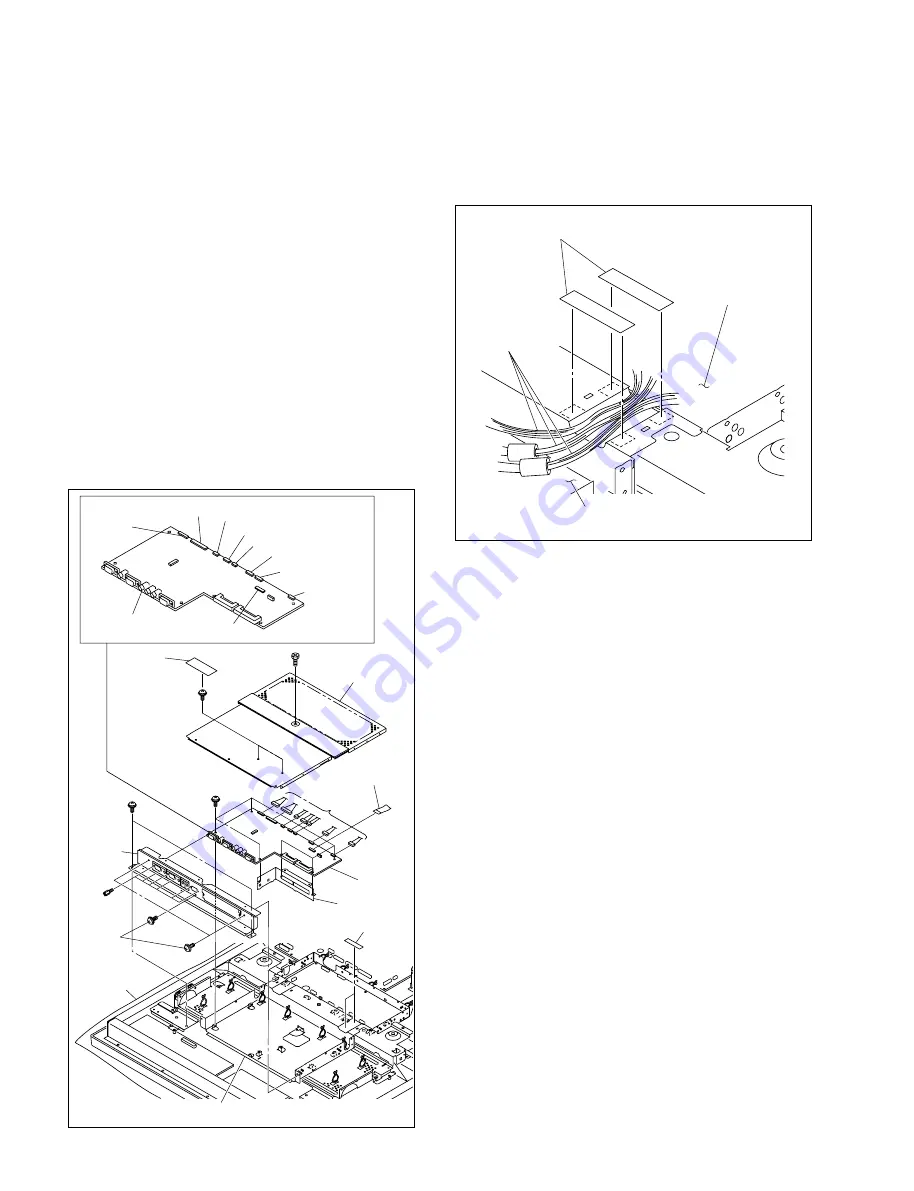
1-3. Replacing the Board
1-3-1. Q Board
1.
Remove the rear cover assembly.
(Refer to Section 1-2-1.)
2.
Remove the bolt, cushion (15
x
25), and two screws
(PSW3
x
8), then remove the Q/B shield cover.
3.
Remove the two screws (PSW3
x
6), three screws
(PSW3
x
8) (black) and six hexagonal screws, then
remove the Q terminal plate.
4.
Move the Q terminal plate slowly in the direction shown
by the arrow, then remove it from the copper foil tape.
5.
Remove the two UL tapes, then disconnect the seven
harnesses and the flexible flat cable connected to the Q
board.
6.
Remove the six screws, then remove the Q board and
partition Q.
PSW
3
x
6
PSW
3
x
6
PSW
3
x
6
PSW
3
x
8
(black)
M8
x
16
CN3007
CN3005CN3008
CN3012
CN3011
CN3001
CN3006
CN3002
Q board
Conductive
cushion
Q board
Hexagonal
screw
Q terminal
plate
Harnesses
Partition Q
UL tapes
Copper foil tape
Q/B shield cover
Flexible flat
cable
Cushion
(15
x
25)
CN3003
7.
Install the Q board in the reverse order of steps 1 to 6.
n
Place and fix the harnesses to connect the Q board and
B board as shown in the illustration.
B board
Q board
Harnesses
UL tapes
Summary of Contents for FWD-50PX1 (English: pgs. 52-97)
Page 48: ......
Page 80: ......
Page 105: ...9 3 FWD 50PX1 9 3 B B B B SIDE SUFFIX 11 A 1 2 3 B C D E F G H ...
Page 107: ...9 5 FWD 50PX1 9 5 Q Q A 1 2 3 4 B C D E F G H Q B SIDE SUFFIX 11 ...
Page 110: ......


