1-11
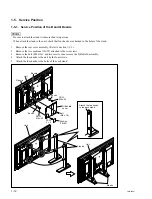
FWD-50PX1
M8
x
16
(Right side as viewed from backside)
M8
x
16
PSW3
x
6
PSW3
x
6
PSW3
x
6
PSW
3
x
6
Main brackets
Cushion
(15
x
25)
Frame (H)
Side frame
Side frame
Plasma display panel
Conductive cushion
Frame (H)
1-4-3. Plasma Display Panel
n
Be sure to replace the plasma display panel with two persons.
1.
Remove the rear cover assembly. (Refer to Section 1-2-1.)
2.
Remove the bezel assembly. (Refer to Section 1-2-2.)
3.
Remove the QB block assembly. (Refer to Section 1-4-1.)
4.
Remove the S board. (Refer to Section 1-3-4.)
5.
Remove the Y drive board. (Refer to Section 1-3-5.)
6.
Remove the X drive board. (Refer to Section 1-3-6.)
7.
Remove the digital video board and interface board. (Refer to Section 1-3-7.)
8.
Remove the power unit. (Refer to 1-4-1.)
9.
Remove the cushions (15
x
25) attached to the heads of the three bolts on the right side as viewed
from backside.
10. Remove the five bolts (M8
x
16), then remove the two main brackets.
11. Remove the four screws (PSW3
x
8), then remove the two frames (H).
12. Remove the six screws (PSW3
x
8), then remove the two side frames.
13. Attach the plasma display panel in the reverse order of steps 1 to 12.
Summary of Contents for FWD-50PX1 (English: pgs. 52-97)
Page 48: ......
Page 80: ......
Page 105: ...9 3 FWD 50PX1 9 3 B B B B SIDE SUFFIX 11 A 1 2 3 B C D E F G H ...
Page 107: ...9 5 FWD 50PX1 9 5 Q Q A 1 2 3 4 B C D E F G H Q B SIDE SUFFIX 11 ...
Page 110: ......


