background image

SERVICE MANUAL
1st Edition

FLAT PANEL DISPLAY

FWD-50PX2

FLAT PANEL DISPLAY SPEAKER SYSTEM

SS-SP50FW

TV STAND

SU-50FW

Summary of Contents for FWD-50PX2
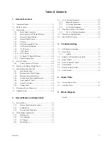
Page 1: ...SERVICE MANUAL 1st Edition FLAT PANEL DISPLAY FWD 50PX2 FLAT PANEL DISPLAY SPEAKER SYSTEM SS SP50FW TV STAND SU 50FW ...

Page 2: ...u befolgen Andere als die angegeben Wartungsarbeiten dürfen nur von Personen ausgeführt werden die eine spezielle Befähigung dazu besitzen AVERTISSEMENT Ce manual est destiné uniquement aux personnes compétentes en charge de l entretien Afin de réduire les risques de décharge électrique d incendie ou de blessure n effectuer que les réparations indiquées dans le mode d emploi à moins d être qualifi...

Page 3: ... og type Levér det brugte batteri tilbage til leverandøren ADVARSEL Lithiumbatteri Eksplosjonsfare Ved utskifting benyttes kun batteri som anbefalt av apparatfabrikanten Brukt batteri returneres apparatleverandøren VARNING Explosionsfara vid felaktigt batteribyte Använd samma batterityp eller en likvärdig typ som rekommenderas av apparattillverkaren Kassera använt batteri enligt gällande föreskrif...

Page 4: ...r oder nach längerer Gebrauchsdauer der Batterien nicht mehr einwandfrei funktioniert Um sicherzugehen kleben Sie die Batteriepole z B mit einem Klebestreifen ab oder geben Sie die Batterien einzeln in einen Plastikbeutel For the customers in the U S A and Canada RECYCLING LITHIUM ION BATTERIES Lithium Ion batteries are recyclable You can help preserve our environment by returning your used rechar...

Page 5: ...6 6 Serial No of Frame 1 15 1 6 7 Voltage Label 1 15 1 7 Warning on Power Connection 1 16 1 8 Unleaded Solder 1 16 2 Service Mode and Adjustment 2 1 Service Mode 2 1 2 1 1 Service Mode Startup Procedure 2 1 2 1 2 Configuration 2 1 2 1 3 Description of Main Items 2 2 2 2 White Balance Adjustment 2 3 2 2 1 Initialization 2 3 2 2 2 AD Calibration 2 3 2 2 3 1PC Signal 2 3 2 2 4 White Balance 2 3 2 3 V...

Page 6: ......

Page 7: ...ew 1 1 Appearance Figure 1 2 Board Location 1 2 3 4 5 6 7 8 9 0 ON SET OFF H2 board H1 board YDB board YDT board Y SUS board Z SUS board XR board XC board T board A board CTRL board XL board L board I board TEMP board TEMP board TEMP board ...

Page 8: ...t on the conductive cushion 1 3 1 Rear Cabinet Assembly Conductive cushion 4 BKM FW10 3 Panel securing screws 1 Side cover 2 Bottom cover 1 Side cover 7 Eighteen screws 8 Fifteen screws 9 Hold the four handles and remove the rear cabinet assembly 0 Rear cabinet assembly Upper side 5 Four screws 6 Four knobs ...

Page 9: ...bly hold the four portions A and remove it from the module frame assembly Place the removed chassis assembly on the conductive cushion Conductive cushion 1 Four screws 6 Two screws 8 Three screws Nine screws 2 Eight screws Two screws Arm Front frame assembly 5 Chassis assembly Filter glass H1 board Bezel assembly 3 Harness Arm Upper side 7 Control button bracket Control button 9 H2 board 4 Harness...

Page 10: ...r side 3 Five screws 7 Five screws 9 Five screws 6 Six connector screws 4 Cover 1 Screw 2 L board 5 I board 8 Interface cover Removing the lithium battery CN501 CN22 CN3 CN19 CN24 CN23 CN29 CN9 CN8 CN15 CN1 P1 P3 A board A board Remove the lithium battery in the direction of the arrow Lithium battery CR 1220 Battery holder ...

Page 11: ... Remove the rear cabinet assembly Refer to Section 1 3 1 Upper side Conductive cushion 1 Five screws 3 Nine screws 5 Two screws 5 Screw CN806 CN805 CN804 CN803 CN801 CN802 CN800 P501 P501 P501 4 G board 6 TEMP board 6 TEMP board 6 TEMP board 2 Shield Conductive cushion Upper side CN802 1 Two screws 2 T board ...

Page 12: ...riented in the upward direction of the main unit DC fan small installation direction Make sure that the label is oriented in the upward direction of the main unit Upper side Conductive cushion 5 Two screws 9 Six screws 3 Two screws 7 Six screws Four screws Four screws 1 Two screws 2 A block assembly 4 Fan bracket large 8 Fan bracket large Fan bracket small 6 DC fan large DC fan large DC fan small ...

Page 13: ...fer to Section 1 3 1 Remove the G board Refer to Section 1 3 4 Upper side 4 Six screws 2 Four screws 1 Two screws 3 Speaker bracket support 3 Speaker bracket support 7 Harness P1 P101 P2 P3 P4 P5 P6 P7 P8 P102 P103 P104 P105 P106 P107 Conductive cushion 5 YDT board 6 YDB board ...

Page 14: ...rd Remove the rear cabinet assembly Refer to Section 1 3 1 Remove the bezel assembly Refer to Section 1 3 2 Remove the A block assembly Refer to Section 1 3 6 Upper side 5 Six screws 1 Four screws 3 Six screws P11 P1 P6 P5 P4 P2 P3 4 Y SUS board 2 Arm 6 Three board brackets Conductive cushion 1 Four screws P2 P300 P200 P105 P106 P107 P3 Upper side Conductive cushion 4 CTRL board 2 Cushion retainer...

Page 15: ... rear cabinet assembly Refer to Section 1 3 1 Remove the bezel assembly Refer to Section 1 3 2 Remove the A block assembly Refer to Section 1 3 6 1 Two screws P153 P152 P3 P2 P1 P151 P4 5 Z SUS board 3 Speaker brackets 2 Z SUS cover 4 Six screws ...

Page 16: ...efer to Section 1 3 4 Remove the A block assembly Refer to Section 1 3 6 1 Four screws 1 Four screws P308 P307 P306 P305 P304 P303 P302 P301 P208 P207 P206 P205 P204 P203 P202 P107 P106 P105 P104 P103 P102 P101 P110 P100 P210 P200 P300 P310 8 XR board 7 XC board 4 Flexible retainers 2 Two frame modules 6 XL board 3 Sixteen screws 5 Five screws Conductive cushion Upper side ...

Page 17: ...1 11 FWD 50PX2 1 3 12 Plasma Display Panel Remove each part Refer to Sections 1 3 1 to 1 3 11 Conductive cushion 1 Plasma display panel ...

Page 18: ...o persons After attaching this unit to the stands make sure that the knobs are securely inserted into the holes of the stands When assembling the service position be sure to repair after removing the rear cabinet Insert the four knobs into the holes of stands Unit Stands 1 Knobs Stands A board 2 Four screws PSW3 x 10 Unit Unit 1 Knobs ...

Page 19: ...play Panel 6 Protection plate for outer box 6 Protection plate for outer box Rear 1 PDP module 2 Cushion upper 2 Cushion upper 3 Cushion lower 3 Cushion lower 4 Inner box upper 7 Outer box upper 5 Inner box lower Front 8 Outer box lower 9 Palette ...

Page 20: ...l Hazard 5 Safety approval label 6 Serial No of frame 7 Voltage label 1 6 1 Identification Label Model Name Bar Code Contains the manufacture No Manufacture No The trade name of LG Electronics Manufactured date Year Month The place Origin Mode Suffix 1 6 2 Warning Label High Voltage 1 6 3 Warning Label Hot Surface 6 cm 1 8 cm WARNING HAZARDVOLTAGE DO NOTTOUCH ELECTRIC POINT HIGH VOLTAGE 6 cm 1 8 c...

Page 21: ...proval Mark UL Approval No 1 6 6 Serial No of Frame 1 6 7 Voltage Label 6 cm 1 8 cm CAUTION MECHANICAL HAZARD DO NOTTOUCH POINTED PART WOUND 7 cm 2 5 cm MODEL POPSON30000 Total Max Watt 500W Max Volts 5 25V 19 8Vs Max Amps 4 0A 2 2A 2 0A 7 cm 2 5 cm K50054000458 P N 33150 C005A 7 cm 2 5 cm MODEL POPSOX30000 All Voltage DC 5 2V Va 60V Vs 195V 115 200 115 N A 100 Max Watt 400W Full White ...

Page 22: ...g use of unleaded solder are printed with a lead free mark LF indicating the solder contains no lead Caution Some printed circuit boards may not come printed with the lead free mark due to their particular size LEAD FREE MARK Pb m Be sure to use the unleaded solder for the printed circuit board printed with the lead free mark The unleaded solder melts at a temperature about 40 dC higher than the o...

Page 23: ...CONT G PC GAIN CONT B DTV CUTOFF BRT R DTV GAIN BRT G CONT R BRT B UPD64012 CONTRAST IFC BRIGHT CBW SATURATION LDLY HUE YOF BRIGHT CIP ASI 0x238 CONT CIP ASI 0x239 SATUR CIP ASI 0x23A TINT CIP ASI 0x23B AUDIO DELAY WHITE BALANCE COLOR TEMP SUB GAIN R GAIN SUB PK G GAIN SUB GAMMA B GAIN SUB CHROMA R OFFSET SUB SHARP G OFFSET SHARP OFFS B OFFSET I P LTI SUB OFFSET PBPR BAL Continued INITIALIZATION E...

Page 24: ...APSED TIME Initializes Operation Time SERIAL NO Initializes Serial Number MODEL NAME Initializes Model Name FILL 0xFF Initializes EEPROM to 0xFF SERIAL MODE Sets Serial Mode to communicate with the set by using RS 232C If INT GOODS is run this is set to SONY SONY This is for user to control the set by using RS 232C as remote controller LG This is for setting white balance ETC This is for developer...

Page 25: ...condition setting Set up the shipment condition 1 Start the on service mode Refer to Section 2 1 1 2 After selecting FOR TEST menu run INIT GOODS n When the setting is completed the unit becomes ON state automatically after power ON OFF 2 2 White Balance Adjustment 2 2 1 Initialization Initialize all information stored in EEPROM 1 Press the ENTER button of the remote controller RM 980 2 Enter the ...

Page 26: ...label on the right upper side of PDP panel For label refer to Section 1 6 2 Turn the volume 1VR700 to be Va Voltage on the label It is normally set in the range between 55 V and 65 V Measuring point 1 2 pins Y SUS board 2 3 3 Vs Voltage Adjustment 1 Check the label on the right upper side of PDP panel For label refer to Section 1 6 2 Then turn the volume 1VR700 to be Va Voltage on the label Measur...

Page 27: ...lume Point GND GND _Vy Vsc 2 4 After Replacing the Y SUS Board 2 4 1 Vsc _ _ _ _ _Vy Volatge Adjustment About detail voltage value see the attached label on the panel Refer to Section 1 6 After measuring at TP proper point control Vsc _Vy volume point if values were wrong case _Vy Vsc ...

Page 28: ...n is being proceeded After processing micom update with ISP program please execute following in order for the unit to maintain Shipping default condition Execute EXCEPT WB in INITIALIZATION Execute COPY WB DATA in WB DEFAULT DATA Execute INIT GOODS in FOR TEST 2 6 DEVICEINFO Section 1 Connect PC to PDP using the serial cable 2 Set the port 1 Select the model FWD 50PX2 2 Select the port COM1 COM2 C...

Page 29: ...e 3 pin of CN1 is the L R output terminal of the audio signal Check the signal using the oscilloscope If there is no signal the A board is the cause of the trouble Otherwise the L board is the cause of the trouble Cause 2 If it is not replace the A board 2 Abnormal sound Cause 1 Replace the L board 3 2 Check Point 3 2 1 A Board LED symptoms 1 No LED flashing Cause 1 G board can t supply 5 V Check ...

Page 30: ...e exhausting tip Check all fuse Check PSU output Va Vs 5 V Check Y and Z boards input voltage Replace the CTRL board Replace the Y board or Z board Check panel appearance Check TCP Replace the XC XL or XR board Replace the CTRL board Check FPC Replace the YDB or YDT board Replace the Y SUS board Replace the CTRL board Replace the YDB board Replace the Y SUS board Replace the CTRL board 3 3 Summary...

Page 31: ...te balance adjustment Refer to Section 2 EDID data input S init Goods Refer to Section 2 n After replacing the parts perform the following adjustments AD calibration adjustment Refer to Section 2 White balance adjustment Refer to Section 2 EDID data input S init Goods Refer to Section 2 n After replacing the G board perform the following adjustments Va Voltage Adjustment Refer to Section 2 3 Vs Vo...

Page 32: ...llowing adjustments AD calibration adjustment Refer to Section 2 White balance adjustment Refer to Section 2 EDID data input S init Goods Refer to Section 2 n After replacing the G board perform the following adjustments Va Voltage Adjustment Refer to Section 2 3 Vs Voltage Adjustment Refer to Section 2 3 n For the replacement parts refer to Section 4 The parts other than those described in Sectio...

Page 33: ...rts When the replacement of those parts is required replace them in the assembly unit LED failure Button failure Yes No Replace the H1 or H2 board Is the H1 or H2 board abnormal Yes Is the connector of H1 or H2 board abnormal No Replace the A board Replace the defective parts n After replacing the parts perform the following adjustments AD calibration adjustment Refer to Section 2 White balance ad...

Page 34: ...in Section 4 are not service parts When the replacement of those parts is required replace them in the assembly unit Remote control is abnormal Yes No Replace the H1 board Is the H1 board abnormal Yes Connect correctly If the trouble persists replace the H1 board Is the connection of H1 board abnormal No Replace the A board n After replacing the parts perform the following adjustments AD calibrati...

Page 35: ...ts supplied by Sony differ from those used for the unit These are because of parts common ality and improvement Parts list has the present standardized repair parts 3 Stock of Parts Parts marked with o at SP Supply Code column of the spare parts list may not be stocked Therefore the delivery date will be delayed 4 Harness Harnesses with no part number are not registered as spare parts In need of r...

Page 36: ...4 2 FWD 50PX2 Screw Kit 4 2 Exploded Views 8 8 8 1 8 8 8 8 8 8 2 8 9 9 8 8 8 8 8 9 8 8 10 11 1 1 c 1 6 7 3 a 4 b 3 7 5 6 12 13 ...

Page 37: ...ered in units of screw kit Sony part No 12 13 INSIDE SCREW KIT 1 339 00 8M 2 1SZZTMP009B 3 1SZZTMF016B 4 1SZZTMF012A 5 332 09 5L 6 1SZZTMF016D 7 1SZZTYT001D a 1NHB0302120 b 1WZZTKK005B c 1SZZTMH005A The numbers encircled by round corresponds to numbers in illustrations OUTSIDE SCREW KIT 8 1SZZTYT003B 9 1SZZTMF016B 1WZZTKK004B 1SZZTMH006B ...

Page 38: ...LVER X 2102 810 1 s BEZEL ASSY BLACK 102 X 2102 794 1 s REAR CABINET ASSY 103 1 789 198 11 s MOUNTED BOARD H2 104 1 789 199 11 s MOUNTED BOARD H1 No Part No SP Description 105 2 657 353 01 s DOOR SIDE 106 2 657 354 01 s DOOR BOTTOM 107 2 657 360 01 s GLASS FILTER 108 X 2109 497 1 o FRAME H ASSY 109 X 2109 498 1 o FRAME V ASSY ...

Page 39: ... 11 s BATTERY LITHIUM CR2032 TYPE 203 1 787 434 11 s FAN DC 204 1 787 437 11 s FAN DC 205 1 789 374 11 s MOUNTED CIRCUIT BOARD A No Part No SP Description 206 1 789 375 11 s MOUNTED CIRCUIT BOARD G 207 1 789 376 11 s MOUNTED CIRCUIT BOARD L 208 1 789 377 11 s MOUNTED CIRCUIT BOARD T 209 1 789 378 11 s MOUNTED CIRCUIT BOARD I ...

Page 40: ...303 1 789 380 11 s MOUNTED CIRCUIT BOARD CTRL 304 1 789 381 11 s MOUNTED CIRCUIT BOARD YDT 305 1 789 382 11 s MOUNTED CIRCUIT BOARD YDB No Part No SP Description 306 1 789 383 11 s MOUNTED CIRCUIT BOARD XL 307 1 789 384 11 s MOUNTED CIRCUIT BOARD XC 308 1 789 385 11 s MOUNTED CIRCUIT BOARD XR 309 1 789 386 11 s MOUNTED CIRCUIT BOARD Y SUS 310 1 802 006 11 s PANEL PLASMA DISPLAY ...

Page 41: ...82 11 s CABLE DVI 406 1 830 999 11 s VIDEO CABLE 407 2 651 871 01 s MANUAL INSTRUCTION JAPANESE ENGLISH FRENCH GERMAN SPANISH ITALIAN SIMPLIFIED CHINESE 408 2 657 560 01 o ACCESSORY BOX 409 2 990 242 01 s HOLDER B PLUG 410 3 613 640 01 o HOLDER C PLUG 411 2 657 461 01 o INDIVIDUAL CARTON 412 2 657 462 01 o CUSHION TOP BOTTOM 413 2 657 463 01 o TRAY BOTTOM 414 2 657 464 01 o BAG PROTECTION 415 2 65...

Page 42: ...o Part No SP Description 501 A 1080 534 A s SPEAKER 50R ASSY RP FOR SS SP50FW W PEARL WHITE A 1080 536 A s SPEAKER 50R ASSY RP FOR SS SP50FW S SILVER 502 A 1080 535 A s SPEAKER 50L ASSY RP FOR SS SP50FW W PEARL WHITE A 1080 537 A s SPEAKER 50L ASSY RP FOR SS SP50FW S SILVER 7 685 661 79 s SCREW BVTP4X12 EP FE ZNBK CM2 ...

Page 43: ...4 9 FWD 50PX2 601 602 SU 50FW No Part No SP Description 601 2 148 620 01 o REAR COVER 602 4 092 541 02 s FOOT Overall ...

Page 44: ...E 11 13 4 12 3 2 1 5 9 7 10 8 6 Board Connections No Part No SP Description 1 1 910 022 06 o CONNECTOR ASSY Y SUS 10P 2 1 910 022 07 o CONNECTOR ASSY Y SUS 4P 3 1 910 019 65 o CONNECTOR ASSY 12P Y SUS 4 1 910 019 66 o CONNECTOR ASSY 7P MAIN 5 1 910 019 67 o CONNECTOR ASSY 12P MAIN 6 1 910 019 68 o CONNECTOR ASSY 8P MAIN 7 1 910 019 69 o CONNECTOR ASSY 12P AU 8 1 910 019 70 o CONNECTOR ASSY 8P RMT ...

Page 45: ...SI510 ODD Even Video 24Bits 24Bit DVI 1080i DVI 1080P RGB 48Bit MST3785MW ADC 170M 8MB x 2 SDRAM LVDX TX Panel CCIR601 16Bits 8MB SDRAM CCIR601 16Bits uPD64015 Video Decoder COMPOSITE Y C Closed Caption M37151 2MB SDRAM CVH SYNC SCART RGB EEPROM 8kB FLASH 1MB SRAM 128kB MICOM SDA5550M PCM1802 ADC NSP 2100A delay Pre Amp TAS5122 Out amp Audio AV S W CXA2069 D Sub BNC DVI EEPROM 128Byte DVI IIC TMDS...

Page 46: ......

Page 47: ...A commercial leakage tester such as the Simpson 229 or RCA WT 540A Follow the manufacturers instructions to use these instruments 2 A battery operated AC milliammeter The Data Precision 245 digital multimeter is suitable for this job 3 Measuring the voltage drop across a resistor by means of a VOM or battery operated AC voltmeter The limit indication is 0 75 V so analog meters must have an accurat...

Page 48: ...Printed in Japan Sony Corporation 2006 1 22 2006 FWD 50PX2 SY E 9 878 387 01 ...

Reviews: