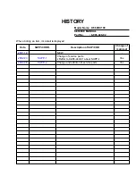
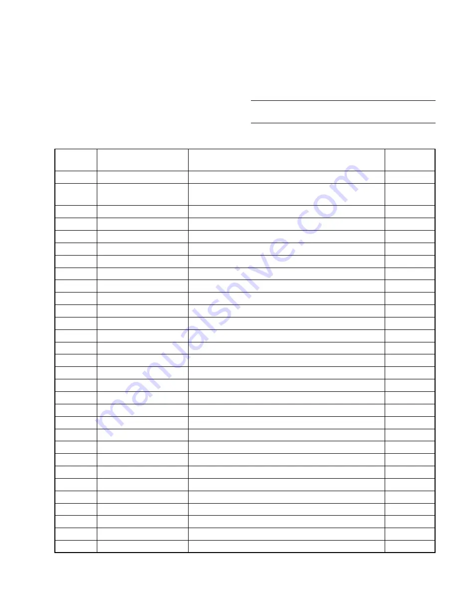
background image

HISTORY

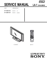
Model Name : KF-60DX100

SERVICE MANUAL
Part No.

: 9-965-440-02

When clicking an item, it’s detail is displayed.

Data

2001.12

2002.03

2004.08

SUPP./CORR.

SUPP.-1

SUPP.-2

Description of SUP/COR

NEW

Change of service parts.

 Reffer to 9-965-440-81 about SUPP.-1.

Change and addition of service parts.

Change of

main text

-

Yes

Yes

Summary of Contents for GRAND WEGA KF 60DX100

Page 1: ... 440 02 When clicking an item it s detail is displayed Data 2001 12 2002 03 2004 08 SUPP CORR SUPP 1 SUPP 2 Description of SUP COR NEW Change of service parts Reffer to 9 965 440 81 about SUPP 1 Change and addition of service parts Change of main text Yes Yes ...

Page 2: ...CHASSIS LA 1 SERVICE MANUAL MODEL COMMANDER DEST LCD PROJECTIONTV KF 60DX100 RM Y910 US KF 60DX100 RM Y910 Canadian KF 60DX100 RM Y910 ...

Page 3: ...X 1 500 mVrms at the maximum volume setting Variable 500 mVrms Fixed Impedance output 2 kiloohms TV Out 1 Video 1 Vp p 75 ohms unbalanced Sync negative Audio 500 mVrms 100 modulation Impedance output 1 kiloohms CONTROL S IN OUT 1 minijacks Component Video Input 2 Y PB PR Y 1 0 Vp p 75 ohms unbalanced sync negative PB 0 7 Vp p 75 ohms PR 0 7 Vp p 75 ohms RF Inputs 2 Converter 1 Speaker Output 15 W ...

Page 4: ...crew is at ground potential See Fig B After correcting the original service problem perform the fol lowing safety checks before releasing the set to the customer 1 Check the area of your repair for unsoldered or poorly sol dered connections Check the entire board surface for solder splashes and bridges 2 Check the interboard wiring to ensure that no wires are pinched or contact high wattage resist...

Page 5: ...3 4 Sub Bright Adjustment 43 3 5 Screen Center Adjustment 43 3 6 Favorites Adjustment 43 TABLE OF CONTENTS 4 DIAGRAMS 4 1 Block Diagram 1 44 Block Diagram 2 45 Block Diagram 3 46 Block Diagram 4 47 Block Diagram 5 48 Block Diagram 6 49 Block Diagram 7 50 Block Diagram 8 51 4 2 Frame Schematic Diagram 52 4 3 Circuit Boards Location 53 4 4 Schematic Diagrams and Printed Wiring Boards 53 1 Schematic ...

Page 6: ...QUAND LA BOBINE DE DEMAGNETISATION EST ENLEVÉE ATTENTION AUX COMPOSANTS RELATIFS À LA SÉCURITÉ LES COMPOSANTS IDENTIFIÉS PAR UNE TRAME ET UNE MARQUE SONT CRITIQUES POUR LA SÉCURITÉ NE LES REMPLACER QUE PAR UNE PIÈCE PORTANT LE NUMÉRO SPECIFIÉ LES RÉGLAGES DE CIRCUIT DONT L IMPORTANCE EST CRITIQUE POUR LA SÉCURITÉ DU FONCTIONNEMENT SONT IDENTIFIÉS DANS LE PRÉSENT MANUEL SUIVRE CES PROCÉDURES LORS D...

Page 7: ... listed below The display 0 means that no malfunctions occurred TIMER STAND BY STEREO LAMP Lamp OFF 3 0 seconds Lamp ON 0 3 seconds Lamp OFF 0 3 seconds Release of TIMER STAND BY indicator blinking The TIMER STAND BY indicator blinking display is released by removing the plug from the power or leaving for 2 minutes One blink is not used for self diagnosis EXAMPLE Diagnosis Items Number of Blinks L...

Page 8: ...ts display to 0 If the results display is not returned to 0 it will not be possible to judge a new malfunction after completing repairs Method of Clearing Results Display Method of Ending Self Diagnosis Screen When ending the self diagnosis screen completely turn the power switch OFF on the remote commander or the main unit 1 Power off Set to the standby mode 2 DISPLAY b Channel 5 b VOL b POWER Se...

Page 9: ... line failure 9 Audio When DC is appeared by audio amp failure at speaker line Then it is detected by MAIN µ com IC9004 and it turns off the main power LAMP Lamp error When lamp is not turned on then pin wl of LCD Engine µ com IC9502 is high checks pin wk of LCD Engine µ com If pin wk is high it is judged lamp is burned out Self Diagnosis block diagram 24 AUDIO PROT 43 LOW B ERR D1902 CN1908 D1901...

Page 10: ... REMOVAL 2 4 SERVICE POSITION 2 Rear cover assembly 1 Six screws BVTP 4 x 16 1 Eight screws BVTP 4 x 16 1 Six screws BVTP 4 x 16 2 OU bracket 3 Three screws BVTP 3 x 12 7 Power block 6 Ballast bracket 6 Ballast cover 5 Two screws BVTP 3 x 12 1 2 Two screws BVWHTP 3 x 12 2 Cabinet stay L 1 Screw BVTP 4 x 16 3 ...

Page 11: ...the no dust or dirt are on the surface contacts the optical unit block assembly Clean the periphery of the set Clean the periphery of the optical unit block assembly in the set the inside of the control panel the surface contacts between the optical unit block assembly and the bottom cabinet and periphery 5 RF antenna switch 4 Two washers 3 Seven screws BVTP 3 x 12 1 Two screws BVTP 4 x 16 7 Termi...

Page 12: ... 11 KF 60DX100 KRM Y910 2 8 G BOARD REMOVAL 2 7 U M BB BC BOARDS REMOVAL 2 M board 3 BB board 4 BC board 1 U board 2 1 Screw BVTP 4 x 16 5 G board 3 Three screws BVTP 3 x 12 4 G bracket assembly ...

Page 13: ...EL BLOCK ASSEMBLY REMOVAL 1 Two screws BVTP 3 x 12 3 A board 2 Two claws 1 Screw BVTP 3 x 12 2 T board 1 Four strikes 5 Six screws BVTP 4 x 16 3 Four strikes 6 Control panel assembly 4 Front cover R assembly 2 Front cover L assembly 4 Control panel block 5 H3 board 3 Connector 2 1 Four screws BVTP 3 x 12 ...

Page 14: ...law 2 Claw 5 Connector 6 H2 board 4 2 Four screws BVTP 4 x 16 4 Screen mirror block assembly 3 Four screws BVTP 4 x 16 1 Connecotr 2 H1 lid 1 Two claws 6 Two screws BVTP 3 X 12 3 Two screws BVTP 4 X 16 4 Fasten tag 5 Connectors 7 H1 board 1 Six screws BVTP 4 x 16 1 Fourteen screws BVTP 4 x 16 3 Mirror cover block assembly 1 Six screws BVTP 4 x 16 2 Two screws BVTP 4 x 16 2 Two screws BVTP 4 x 16 B...

Page 15: ...mbly 7 Contrast screen assembly 4 Diffusion plate 60F assembly 5 Diffusion plate 60L assembly 6 Bezel assembly 3 Screen holder S assembly 1 Ten screws BVTP 4 x 16 1 Six screws BVTP 4 x 16 1 Four screws BVTP 4 x 16 1 Two screws BVTP 4 x 16 5 Two screws BVTP 4 x 16 3 Two screws BVTP 4 x 16 2 Squawker block L assembly 6 Squawker block R assembly 4 Woofer block L assembly 8 Woofer block R assembly 7 T...

Page 16: ...KERS REMOVAL 1 Two screws BVTP 4 x 16 6 Speaker 2cm 2 Speaker 13 x 7cm 4 Fasten tags 5 Fasten tags 1 Two screws BVTP 4 x 16 3 Two screws BVTP 3 x 12 1 Four screws BVTP 4 x 16 3 Four screws BVTP 4 x 16 2 Two mirror holders L 4 Two mirror holders R 5 Mirror ...

Page 17: ...to select the adjustment item 3 Press 3 or 6 on the remote commander to change the data 4 Press 2 or 5 ontheremotecommandertoselectthecategory Every time you press 2 Category up Service mode changes in the order as shown below LCD Projector Engine 3D COMB MCP ADJ3 MID1 L001AOI CCD OP D GM TG ID 2103 1 VID ADJ MID2 L001POS S L001OUT D GM IM 2103 2 USER STD HV POS AD MID3 L001SCALE H POS SHI P BOOST...

Page 18: ... 1 4 Adjusting Buttons and Indicator Commander Function Button Mode Description MUTING ENTER WRITE Writes data to NVM ENTER READ Reads data from NVM 8 ENTER RESET Set the shipping condition 7 ENTER INT Service data initialization Not stored Be sure not to use usually FUNCTION OF KEYS ON COMMANDER 1 Changes adjustment item item No moves up 4 Changes adjustment item item No moves down 2 Changes adju...

Page 19: ... center frequency 0 3 3 Table 3 19 YPFG Y peaking filter BPF gain 0 15 7 RF Video CV S Component 20 YHCO Y output high frequency component coring 0 3 0 13 VTRH 1 1 1 21 YHCG Y output high frequency component coring gain 0 1 0 14 VTRR 1 1 1 22 HSSL H sync slice level 0 15 12 15 LDSR 2 2 2 23 VSSL V sync slice level 0 15 8 35 CC3N 0 0 0 24 ADCL ADC clock delay 0 3 3 25 D2GA Moving detection gain 0 7...

Page 20: ... 0 0 13 LPF Y Cb Cr output LPF on off 0 1 1 1 1 1 14 AFCG AFC loop gain PLL between H sync H VCO 0 1 1 0 0 15 CDMD V countdown system mode selector 0 3 3 3 3 16 SSMD H V sync slide level setting 0 3 0 0 0 17 HMSK Masking of macrovision signal on off 0 1 1 1 1 18 HALI H automatic adjustment on off 0 1 0 0 0 19 PPHA H TIM phase adjustment video 0 15 6 8 8 One screen Mild Others 20 CBOF Cb EXT Cb off...

Page 21: ...er on off 0 1 0 0 0 12 TRAP Y block chroma trap filter on off 0 1 0 0 0 13 LPF Y Cb Cr output LPF on off 0 1 1 1 1 RF Video 14 AFCG AFC loop gain PLL between H sync H VCO 0 1 1 0 15 CDMD V countdown system mode selector 0 3 3 3 16 SSMD H V sync slide level setting 0 3 0 0 17 HMSK Masking of macrovision signal on off 0 1 1 1 18 HALI H automatic adjustment on off 0 1 0 0 19 PPHA H TIM phase adjustme...

Page 22: ...0 0 0 0 12 LDH Luminance determined histogram Snow color adjustment by green stretch 0 1 0 1 1 1 1 1 1 1 13 SNOW 0 1 1 1 1 1 1 1 1 1 Comon 14 WLB Window letterbox format 0 1 0 P BOOST 3 No Name 0 1 2 3 4 5 6 7 0 CDS Color dependent sharpness on off 0 1 1 1 1 1 1 1 1 1 1 CTI Color transient improvement on off 0 1 0 0 0 0 0 0 0 0 2 WPO White point stretch on off 0 1 1 1 1 1 1 1 1 1 3 DBL Blue stretc...

Page 23: ...7 8 7 7 1 SHUE Hue center control 0 15 8 8 8 8 8 7 2 RYR Sets R Y component in R Y axes 0 15 2 2 2 2 4 4 0 0 0 0 3 RYB Sets B Y component in R Y axes 0 15 10 10 10 10 12 12 4 4 0 0 4 GYR Sets R Y component in G Y axes 0 15 10 10 10 12 10 10 0 0 0 0 5 GYB Sets B Y component in G Y axes 0 15 8 8 8 5 5 5 0 0 0 0 MCP ADJ3 No Name Mild Others Mild Others Mild Others Mild Others Mild Others Mild Others ...

Page 24: ...21 26 17 26 21 26 2 UCOL Color gain control 0 63 31 31 35 31 31 31 35 31 3 UHUE Hue control 0 63 31 31 31 31 31 31 31 31 4 USHP Sharpness gain control 0 63 37 37 31 31 37 37 31 31 5 UHWT Dynamic color on off 0 1 0 0 0 0 2 1 0 1 6 UTMP Color temperature 9 Warm 1 Neutral 2 Cool 0 3 2 1 0 1 480i 480i Vivid Standard Movie Mild Vivid Standard Movie Mild Vivid Standard Movie Mild Vivid Standard Movie Mi...

Page 25: ...n LRGB2 system 0 15 15 15 PABL Sets level detection DC at RGB OUT of PEAK ABL 0 15 15 16 BLKB RGB OUT bottom limiter level control 0 15 5 Item Function Data Range Data 2151 No Name 0 MTRX Matrix out 0 3 0 0 1 1 COMMON 1 GAIN Gain select 0 3 0 2 CBGN Cb gain 0 15 9 3 VTC V TC 0 3 1 4 HWID H width 0 3 1 5 HSEP HSEP select 0 1 COMMON 6 TEST Test 0 1 0 7 FRGB 0 1 0 1080i Others 8 HMSK H sync masking i...

Page 26: ... size 0 255 35 31 Comon 18 PDHP P P large mode H position 0 255 99 19 PDVP P P large mode V position 0 255 55 20 PDHS P P large mode H size 0 255 117 21 PDVS P P large mode V size 0 255 60 22 DPSW Display PLL switch 0 1 1 23 MDL Model select 16 9 4 3 0 1 0 Normal Others 24 BCOL Background Y level 0 15 0 0 Item Function Data Range Comon 480i 480p 720i 1080i Parent 1080i Child Favorite 0 230 0 120 M...

Page 27: ...ve area even position 0 63 25 55 54 3 VDVS VDO V active area line size 0 255 56 111 165 4 VDVO VDO V active area odd position 0 3 0 0 0 0 5 VCPO VDO clamp pulse output timing 0 255 95 70 40 40 6 VCWD VDO clamp pulse width VDO Y C delay 0 7 3 3 3 3 7 VYCD 0 63 0 0 0 0 8 VSTP VDO PLL phase detect stop line count 0 255 146 9 VSTT VDO PLL phase detect start line count 0 15 0 Common 10 VHSC VDO H sync ...

Page 28: ...evel 0 3 0 0 0 0 0 0 0 0 0 0 0 0 18 MVCE Main V enhance C enhancement level 0 7 0 0 0 0 0 0 0 0 0 0 0 0 0 POP Table select 0 23 POP 12 POP 13 POP 14 POP 15 POP 16 POP 17 POP 18 POP 19 POP 20 POP 21 POP 22 POP 23 1 MHLY Main H LPF Y coefficient select 0 3 1 0 1 1 1 2 2 2 0 0 0 0 2 MHLC Main H LPF C coefficient select 0 3 0 0 0 0 0 2 2 2 0 0 0 0 3 MVLY Main V LPF Y coefficient select 0 3 0 0 0 0 0 0...

Page 29: ...n write picture vertical size 0 255 120 120 60 60 120 120 3 MRHP Main read picture horizontal position 0 255 0 0 0 0 0 0 4 MRVP Main read picture vertical position 0 255 30 11 30 11 30 11 5 MRHS Main read picture horizontal size 0 255 164 164 227 227 174 174 6 MRVS Main read picture vertical size Not used Not used Not used Not used Not used Not used Not used Not used Not used Not used Not used Not...

Page 30: ...ed to TDA9178 NLAMP setting 0 15 Table 1 11 NLMP TDA9178 NLAMP 0 15 0 2 4 5 x2 Offset for TDA9178 NLAMP 12 PKNG Related to TDA9178 PKNG setting 0 15 Table 1 12 PKNG TDA9178 PKNG 0 15 0 2 3 4 x4 Offset for TDA9178 PKNG 13 CRNG Related to TDA9178 CRNG setting 0 15 Table 1 13 CRNG TDA9178 CRNG 0 15 0 2 5 4 x4 Offset for TDA9178 CRNG 1 SNFX 0 SNNR will be controled by Micro which depends on the value ...

Page 31: ...ut horizontal sync signal OHSB at all times Disables the output of OHSB generated simultaneously with OVSB Specifies decimal point place of factor in vertical interpolation table Specifies decimal point place of factor in vertical enlarged interpolation table Specifies decimal point place of factor in horizontal reduced interpolation table L001ENH No Name 0 SCENH 0 3 Table1 1 VCOFEN Specifies vert...

Page 32: ... 34 Mild 35 0 SCENH 1 1 1 1 1 1 1 1 1 1 1 1 1 VCOFEN 0 0 0 0 0 0 0 0 0 0 0 0 2 VCOFSEL 1 1 1 1 1 1 1 1 1 1 1 1 3 HCOFEN 1 1 1 1 1 1 1 1 1 1 1 1 4 HCOFSEL 0 0 0 0 0 0 0 0 0 0 0 0 PICMD Vivid 36 Standard 37 Movie 38 Mild 39 Vivid 40 Standard 41 Movie 42 Mild 43 Vivid 44 Standard 45 Movie 46 Mild 47 0 SCENH 1 1 1 1 4 4 5 1 0 0 1 1 1 VCOFEN 0 0 0 0 0 0 0 0 0 0 0 0 2 VCOFSEL 1 1 1 1 1 1 1 1 5 5 1 1 3 H...

Page 33: ... 1 1 0 0 0 0 16 AOISEL 0 0 0 0 0 0 0 0 0 0 17 EYD 3 0 4 3 2 1 0 0 0 0 18 YDANEN 1 0 1 1 0 0 0 0 0 0 19 YDAN 3 0 2 2 0 0 0 0 0 0 20 HICLPEN 0 0 0 0 0 0 0 0 0 0 21 HICLPH 31 31 31 31 31 31 0 0 0 0 0 SCENH 10 11 12 13 14 15 5 HSRK COFEN 0 0 0 0 0 0 6 SVDANEN 0 0 0 0 0 0 7 SVDAN 0 0 0 0 0 0 8 SVCLPEN 0 0 0 0 0 0 9 SVCLP 0 0 0 0 0 0 10 SHDANEN 0 0 0 0 0 0 11 SHDAN 0 0 0 0 0 0 12 SHCLPEN 0 0 0 0 0 0 13 ...

Page 34: ...he timing with clocks ICK at which false IVS signal is generated Specifies propagation method of the register having IVS sync control Specifies propagation method of the register having OVS sync control L001OACT No Name 0 OACTAVSTL Sets output image start point coordinate in vertical direction 0 255 0 1 OACTAVSTU Sets output image start point coordinate in vertical direction 0 15 0 2 AVST ATEN 0 1...

Page 35: ...ll Wide Zoom 480i 480i 480i Except Mild Mild Except Mild Mild Except Mild Mild 0 1 2 3 4 5 6 7 8 9 10 11 12 13 14 0 IACTAHSTL 127 129 127 127 125 124 127 127 127 125 124 1 IACTAHSTU 0 0 0 0 0 0 0 0 0 0 0 2 IACTAVSTL 24 24 24 24 24 24 24 30 24 24 24 3 IACTAVSTU 0 0 0 0 0 0 0 0 0 0 0 4 OVSDLY 22 24 20 22 24 20 21 27 21 23 19 5 OHSCYCL 35 35 35 35 35 35 35 30 35 35 35 6 OHSCYCU 3 3 3 3 3 3 3 3 3 3 3 ...

Page 36: ...rite D GM TG No Name 0 INV CTL Invert control 0 1 0 1 POS CTL Position control 0 15 11 2 H POS TG H position 0 255 11 3 V POS H TG V position H 0 255 4 4 V POS D TG V position dot 0 255 30 5 HST POL HST polarity 0 1 0 6 HCK W HCK width 0 1 0 7 HST POS HST position 0 63 15 8 HCK POL HCK polarity 0 1 1 9 HCK A INV HCK auto invert 0 1 0 10 VST POL VST polarity 0 1 0 11 VST A INV VST auto invert 0 1 0...

Page 37: ...5 Table1 30 G PICT Picture 0 127 100 31 G BRIGHT Brightness 0 127 57 Item Function Data Range Data Table1 26 0 0 1 2 3 4 5 6 7 8 9 10 11 12 13 14 15 27 APC TH 255 10 10 10 5 5 10 10 10 10 10 10 10 10 10 10 28 APC LIMT 0 20 20 30 30 30 30 30 30 30 30 30 30 30 30 30 29 APC LEV 0 80 60 45 45 100 45 45 45 45 45 45 45 45 45 45 Table2 WIDE FULL NORMAL 0 or 2 INP RF 0 Video 1 Component 8 SCMD 480i 0 480p...

Page 38: ...H pulse select 0 3 1 12 AGC SHP W AGC SH pulse width 0 63 2 Item Function Data Range Data Item Function Data Range Data D GM TPN No Name 0 T PATN SW Test pattern switch 0 1 0 1 T SIG SEL Test signal select 0 7 1 2 PATN DIR Pattern direction 0 1 1 3 SIG LV DIR Signal level direction 0 1 0 4 T PATN PIT Test pattern pitch 0 255 144 5 B LV Blue test pattern level 0 63 25 6 G LV Green test pattern leve...

Page 39: ... 0 99 10 MIN OSD E No Name 0 VPOS Engine service indication V position 0 255 8 1 HPOS Engine service indication H position 0 255 22 OPTION E No Name 0 LAMP TIME Lamp lighting time 0 1 LAMP OFF Time from power off to lamp off 0 0 sec 1 5 sec 0 255 1 2 FAN OFF Time to FAN stop 0 2 min 1 2 min 0 255 0 3 FAN1 RPM1 Rotating speed of FAN for optics on normal condition 0 3 2 4 FAN1 RPM2 Rotating speed of...

Page 40: ...fference between black level and white level is 1 2 Vp p 1 STEP Adjustment positions Category tem Left screen 2103 1 2 SCON Right screen 2103 2 2 SCON 5 After the adjustment finished return the data set in 2 to original values and write the data by pressing the MUTE ENTER buttons on the remote commander 3 Video Input Adjustment 1 Enter the Video STEP 100 signal including 0IRE and 100IRE and set th...

Page 41: ...ata in each mode Adjustment conditions PICTURE MODE Vivid Category Item Data MCP ADJ1 2 GDRV 50 3 GCUT 40 VID ADJ 1 GAM 0 2 DCTN 0 3 DPIC 0 USER STD 2 UCOL 31 3 UHUE 31 9 UCOF 31 10 UHOF 31 2 Connect an oscilloscope to the CN702 pin 1 TP744 on the BB board 1 5 Vp p 2 RF Input Adjustment 1 Enter the RF color bar 75 signal 2 Set the adjustment conditions in 1 Preparation and further set the followin...

Page 42: ...nditions in 1 Preparation and further set the following data Adjustment conditions Category Item Data P BOOST1 0 BSET 0 2103 1 22 ATPD 0 23 DCTR 0 3 Measure the waveform and repeat the SCOL and SHUE adjustments so that VB1 VB4 and VB2 VB3 Adjustment position Category Item MCP ADJ2 0 SCOL 1 SHUE 4 After the adjustment finished return the data set in 2 to original values and write the data by pressi...

Page 43: ...r 11 Enter the Component 720p signal Set same values as those adjusted in 9 and write the data by pressing the MUTE ENTER buttons on the remote commander GND H L C O 3 3 VERTICAL STRIPE ADJUSTMENT 1 Set the following adjustment conditions and display the test pattern Adjustment conditions Category Item Data D GM TEST 2 G LUT SW 0 D GM TPN 0 T PATN SW 1 1 T SIG SEL 0 2 PATN DIR 1 3 SIG LV DIR 0 5 B...

Page 44: ...ised take care not to cause the white blurring 3 If the SUB CON value was changed check the white balance and repeat adjustment to attain best sub brightness sub contrast and white balance 4 After the adjustment finished write the data by pressing the MUTE ENTER buttons on the remote commander 3 5 SCREEN CENTER ADJUSTMENT 1 Enter the RF monoscope signal 2 Adjust so that the picture is displayed in...

Page 45: ...V OUT 4 ACO IC2302 10V REG 4 VOUT 12V 10V 5 VIN 7 AYO C1 MAIN TU V A1 MAIN TU L A3 MAIN TU R C3 SUB TU V C4 SUB TU L R A31 PS V C25 DAT1 C27 CLK1 SDA SCL SDA SCL 25 F IN Q2016 2022 BUFFER Q2017 2020 2025 2027 BUFFER Q2019 2021 2024 2028 BUFFER 41 MONITOR V OUT 63 RF MAIN V 62 RF MAIN L 64 RF MAIN R Q2012 2026 BUFFER AMP FILTER FILTER BP FILTER BP FILTER 8 S V 9 RF SUB L 11 RF SUB R 10 MULTI V IN 3...

Page 46: ...IN C C31 MAIN Y C7 SUB Y C6 SUB C C10 D1 Y C9 D1 CB C8 D1 CR C13 D2 Y C12 D2 CB C11 D2 CR C32 PS V C5 FSC SUB Y SUB C D1 Y D1 CB D1 CR D2 Y D2 CB D2 CR PS V FSC C1 SDA1 A1 SCL1 C2 YUV SW A3 BLOCK M C3 BLOCK S YUV SW BLOCK M BLOCK S MILD CONT A5 MILD CONT Y C20 Y CB C22 CB CR C21 CR SEL Y OUT C29 SEL Y OUT SEL CB OUT C27 SEL CB OUT SEL CR OUT C28 SEL CR OUT DRC SEL1 C19 DRC SEL1 DRC SEL2 A19 DRC SE...

Page 47: ...N MILD CONT YUV SW BLOCK M BLOCK S 18 FAN2 H 19 FAN2 L 20 FAN1 H 21 FAN1 L 22 FAN CTL 23 FAN PRT 50 HV DET 39 LAMP PRT 40 LAMP CTL LAMP PRT LAMP CTL 49 LAMP COV 42 KEY1 44 STEREO LED 43 STBY LED 45 LAMP LED 47 SIRCS 48 P ON STEREO LED STBY LED LAMP LED SIRCS P ON IC1903 3 3V REG O 4 5V BB 3 3V I IC1904 9V REG O 11V 9V I IC1910 15V REG O 17V 15V I IC1911 3 3V REG O 4 5V 3 3C I CN1907 3 SCLK E 4 ENB...

Page 48: ...IN 1 SC 19 YOUT 17 UOUT 16 VOUT 14 SDA 11 SCL DAT1 CLK1 IC3002 ID 1 DECODER 6 VSIN 7 VDIN 10 SDA SUB CR SUB CB SUB Y D1 Y Y CB CR HD M VD M HD M VD M HD S VD S D1 CB HD S VD S D1 CR D2 Y D2 CB D2 CR 9 SCL 12 XO 13 XI IC3006 YCT SELECT 1 Y M 3 CB M 13 CR M 2 Y S 5 CB S 12 CR S 15 Y O 4 CB O 14 CR O 9 M S 10 M S 11 M S 24 22 23 24 SCP 19 XTAL SDA SCL DAT1 CLK1 VD M HD M 48 50 SDA 9 RST SCL DAT1 CLK1...

Page 49: ...1 READ PLL 3 VCO OUT 5 FINB 6 PFD OUT 12 VCO IN 4 FINA DAT1 CLK1 TH Y TH CB TH CR TH HS TH VS 76 DXT2IN X502 74 175824MHz 1 2 3 4 5 6 7 8 9 10 11 E1 TO BLOCK DIAGRAM 3 A 2 2 BOARD CN1923 TO BLOCK DIAGRAM 6 BB 2 2 BOARD 2 5VA 3 4 1 88 91 DXT1OUT DXT1IN X501 18 543956MHz 6 I 13 17 I 24 D A 1 I D A 8 D B 1 I D B 8 174 I 181 164 I 171 DIY0 I DIY7 DIC0 I DIC7 147 I 154 133 I 140 DBO2 I DBO9 DR02 I DR09...

Page 50: ... HOLD XVDO HS PLL HOLD 9 O DRC CD SEL1 16 FULL NORMAL 10 O DRC CD SEL2 64 OSD H SYNC 63 OSD V SYNC 68 B 69 G 66 OSD YS 53 SUB BUSY 57 B INT 96 D1 99 D2 98 C1 100 C2 CLK1 DAT1 SCL1 SDA1 SCL1 SDA1 32 5V 9V 2 4 9V 9V 1 34 5V A5 1 A5 2 D3 3 1 2 9V 14 M OSD B 13 M OSD G 12 M OSD R 11 M YSYM 8 E OSD G 7 E OSD R 6 E YSYM M OSD B M OSD G M OSD R M YSYM E OSD G 9 E OSD B E OSD R E YSYM M OSD B M OSD G M OS...

Page 51: ... SW 94 KEY1 71 MILD CONT 46 MPWR 48 STEREO LED 49 STBY TIMER LED 44 OCP E POW WATCH 45 X0 42 X1 43 DOT 71 DOTX 72 TRAP 53 BINT 57 E MUTE 59 POW CTL 1 SCLK2 100 SDAT2 99 WP M 77 X COM 13 A 9 B 10 SDAT1 96 SCLK1 98 84 CPU RST 22 YM Q9006 BUFFER Q9514 BUFFER Q9506 INVERTER Q9505 9507 9509 LAMP CONTROL Q9513 BUFFER Q9512 BUFFER Q9515 BUFFER 3 DAT R SEL Q9024 BUFFER IC9513 INVERTER 4 2 IC9512 INVERTER ...

Page 52: ... BIMETAL SWITCH Q1606 CONVERTER Q4503 LED DRIVE Q4508 LED DRIVE Q4509 LED DRIVE Q1603 RELAY DRIVE Q1607 CONVERTER Q1601 CONVERTER D1620 11V RECT D1623 5V RECT 8 18 9 D1624 AU 15V RECT D1625 AU 15V RECT D1614 STBY7V RECT D1621 17V RECT D1613 1616 1617 33V RECT M TO BLOCK DIAGRAM 3 A 2 2 BOARD CN1901 CN4401 KEY1 3 S4411 MENU K TO BLOCK DIAGRAM 3 A 2 2 BOARD CN1909 CN1606 AU 15V 1 AU 15V 7 AU 15V 2 A...

Page 53: ...OMR PSIG OG PSIG EG VSSG AU GND AU GND AU GND AU 15V AU 15V AU 15V AU 15V A M 270V TO C SHIELD TO G SHIELD LAMP COV FAN1 POW FAN1 PR FAN2 POW FAN2 PR HV DET OSD BUSY GND GND GND GND 4 5V 4 5V 4 5V 4 5V GND GND 5V 5V GND GND GND GND GND 11V 11V 11V 11V SUB 7V POWER CTL GND 17V 33V GND G H GND V GND R GND B GND HOLD PSIG OB PSIG EB PST HVDD VCOM SOUT VVDD VSS DWN VST VCK ENB COML VSS HCK2 HCK1 HST R...

Page 54: ...tion to where the line is to be connected is printed at the end of each line For example TO A1 3 A2 3_1 means the line is connected to Ref No 1 of A 1 3 and A 2 3 schematic diagrams TO A1 3 A2 3_1 Ref No Name of divided schematic diagram G D S B1 E1 C2 B2 C1 E2 2 3 4 5 6 7 8 9 0 qa qs qf qh qj qk 1 G D S B2 E2 C1 B1 C2 E1 B2 E2 C1 B1 C2 E1 B2 E2 C1 B1 C2 E1 ql B1 E1 E2 C1 B2 C2 w B1 E2 C1 C2 ws wd...

Page 55: ...D1933 C1963 C1991 C1940 C1990 C1962 R1983 R1982 R1945 R1981 R1988 R1985 R1984 CN1920 C1989 C1988 CN1922 CN1914 C1931 C1943 C1941 D1911 IC1907 C1933 D1914 C1932 C1944 C1942 D1912 IC1908 C1934 C1911 C1921 IC1903 C1913 C1920 C1916 C1914 C1923 C1917 C1915 C1928 CN1904 R1906 C1958 C1960 IC1911 C1959 C1956 R1964 R1965 C1953 C1952 C1910 C1918 D1909 D1920 D1921 C1980 D1908 IC1913 Q1908 R1974 R1973 R1972 L...

Page 56: ...A19 A20 A21 A22 A23 A24 A25 A26 A27 A28 A29 A30 A31 A32 C1 C2 C3 C4 C5 C6 C7 C8 C9 C10 C11 C12 C13 C14 C15 C16 C17 C18 C19 C20 C21 C22 C23 C24 C25 C26 C27 C28 C29 C30 C31 C32 1 1 1 1 L1008 L1007 C1088 L1009 Q1014 R1068 L1111 L1112 C1133 C1132 L1113 C1122 Q1127 R1135 R1131 R1138 R1137 R1136 D1004 D1115 R1048 C1129 C1128 C1117 Q1121 C1124 C1099 C1083 C1091 Q1007 C1094 TU1001 Q1002 R1046 R1056 Q1108 ...

Page 57: ...R1238 R1267 R1268 R1272 R1231 R1233 C1240 R1236 R1252 Q1215 R1258 R1257 R1250 R1227 R1222 R1232 C1236 R1225 R1226 Q1201 Q1202 C1255 C1256 R1241 R1247 R1249 R1263 C1231 C1261 D1212 R1269 C1359 C1373 C1375 C1382 C1383 C1390 C1391 C1389 CM1901 R1211 R1212 C1234 IC1201 C1228 C1260 D1204 R1344 R1355 R1343 R1358 R1368 R1392 IC1203 C1354 R1220 R1221 R1218 R1219 R1206 R1207 R1208 R1209 R1264 CN1909 CN1919...

Page 58: ...R307 R308 R309 R313 R314 R315 R316 R317 R318 R319 R329 R330 R334 R336 R338 R345 R346 R347 R348 R350 R397 R6302 R323 R321 R335 R328 R337 R333 C314 R349 R332 R326 R324 R331 C311 RB301 RB302 RB303 RB304 RB305 RB306 C312 R389 R390 R391 C301 C310 C395 C396 C302 C305 C306 C308 C313 C316 C317 C318 C319 C320 C321 C323 C324 C325 C326 C327 C328 C329 C331 C334 C335 C336 C339 C341 C342 C343 C344 C345 C346 C34...

Page 59: ...458 R459 C382 C383 IC307 Q306 TP301 TP302 TP303 TP304 TP305 R364 Q213 Q216 C384 C385 L311 L314 IC306 L306 L309 L312 100 6 3V AL CP 47 16V AL CP 47 16V AL CP 4 7 35V AL CP 47 16V AL CP 47 16V AL CP 47 16V AL CP 10 16V AL CP TLC5733AIPM 3CH 8BIT A D 2PD601AR BUFFER 2PD601AR BUFFER 2PD601AR VCC DROP 2 2k 1 16W CHIP 100 1 16W CHIP 820 1 16W CHIP 2 2k 1 16W CHIP 1k 1 16W CHIP 680k 1 16W CHIP 5 1k 1 16W...

Page 60: ...722 C7723 R7759 R7760 R7765 C7725 C7729 R7754 R7755 R7756 R7740 R7741 R7742 R7743 R7744 R7745 IC7703 IC7704 R7773 R7775 TP7701 TP7702 TP7703 TP7704 TP7705 TP7706 TP7708 TP7709 TP720 TP721 TP722 TP723 TP724 TP725 TP726 TP727 TP728 TP729 TP730 TP731 TP732 TP733 TP734 TP735 TP736 TP737 Q7711 Q7712 R062 R063 R061 L7705 R7761 C7721 R7757 C7724 IC7705 C7726 R7764 C7727 Q7713 R7767 R7762 R7763 TP7707 R77...

Page 61: ... R024 R027 R028 R029 C001 C002 C004 IC003 Q001 Q004 X001 D001 D002 D003 D004 L001 R026 R016 C003 R038 R039 R040 R041 C007 C008 C009 C010 Q002 Q003 R031 R034 R035 R036 R037 R042 C006 R018 R025 R014 R017 R032 R030 C011 C012 R043 R044 R004 L002 Q005 Q006 R045 R046 R047 R048 R050 C013 TP001 TP002 TP003 TP004 R020 C014 C015 R051 R052 R054 R008 C016 R053 IC005 IC004 R055 R056 R057 R058 R059 R033 R064 IC...

Page 62: ...07 R6532 R6533 C659 R501 Q501 TP501 R506 R505 C506 C507 C508 R509 R511 R512 Q502 R508 R513 C502 C522 C524 C528 C529 C530 C525 C526 C527 C534 IC504 R523 R527 R534 C541 RB505 C552 C553 RB506 C556 C542 R532 C520 C519 C518 C521 R516 C513 C514 R510 C512 C515 R518 C531 C532 C533 C535 R515 IC503 C536 C538 C537 C544 IC505 R546 R559 C560 R548 C555 R549 R541 C558 R557 R558 R542 R540 R539 R538 R537 IC403 1 5...

Page 63: ...2 Q523 X502 C569 C573 C586 C587 C608 C609 C610 C611 C612 C634 R574 R576 R578 R579 R581 R582 R594 R595 R597 R598 R599 R606 R607 R608 R609 R615 R618 R622 R627 R628 R630 R631 R633 R637 R638 R6509 R6511 R6512 R6513 R6514 R6542 R6503 R6501 R6520 C661 R587 R583 R6508 R596 R613 R610 R593 IC513 R6521 C635 R580 IC506 C563 R553 R536 R526 C501 C503 IC514 C509 C549 C583 C626 C638 C639 C559 C570 C574 C575 C578...

Page 64: ...08 R7725 R7729 10 16V AL CP 10 16V AL CP 47 16V AL CP 47 16V AL CP 10 16V AL CP 10 16V AL CP CXD2309Q T6 D A 100 4 100 4 100 4 100 4 100 4 100 4 3 3k 1 16W CHIP 2 2k 1 16W RN CP 3 3k 1 16W RN CP 100 1 16W CHIP 100 1 16W CHIP 100 1 16W CHIP 220 1 16W RN CP 220 1 16W RN CP 2 2k 1 16W RN CP 220 1 16W RN CP 2 2k 1 16W RN CP DTC114EKA TRAP SW DTC114EKA TRAP SW 0 01 25V B CHIP 0 01 25V B CHIP 0 01 25V B...

Page 65: ...20 R700 C704 C730 R706 C706 C727 C780 R699 R710 R714 R715 R718 R739 R746 R748 R750 C776 R713 R764 IC703 TP740 TP741 TP742 TP743 TP744 TP745 CN900 R702 R727 R840 R842 R701 R909 2PB709AR 100 1 16W CHIP 2PB709AR IK DET 2PB709AR IK DET 2PB709AR IK DET MA111 MA111 MA111 33k 1 16W RN CP 10k 1 16W CHIP 4 7k 1 16W CHIP 100 1 16W CHIP 100 1 16W CHIP 100 1 16W CHIP 47 16V AL CP 100 1 16W CHIP 10 16V AL CP 2...

Page 66: ...1 25V B CHIP 0 01 25V B CHIP 0 01 25V B CHIP 0 01 25V B CHIP 0 01 25V B CHIP 0 01 25V B CHIP 0 01 25V B CHIP 0 01 25V B CHIP 0 01 25V B CHIP 0 01 25V B CHIP 0 01 25V B CHIP 0 CHIP 0 CHIP M52055FP CHIP 47 16V AL CP 1 2k 1 5k 1 16W CHIP 1 5k 1 16W CHIP 1 2k 1 16W CHIP 1 2k 1 16W CHIP 1 2k 1 16W CHIP 1 2k 1 16W CHIP 1 2k 1 16W CHIP 1 2k 1 16W CHIP 1 5k 1 16W CHIP 1 5k 1 16W CHIP 1 2k 1 16W CHIP 1 5k ...

Page 67: ...65 R3266 R3267 R3268 R3269 R3270 R3271 R3272 R3273 R3274 C3106 C3120 C3121 C3122 C3123 C3124 C3125 C3126 C3127 C3128 C3129 C3130 C3131 C3132 C3133 C3134 C3135 C3136 C3137 C3138 C3139 C3140 C3141 C3142 C3143 C3144 C3145 C3146 C3147 C3149 C3150 C3151 C3152 C3154 C3155 C3156 C3157 C3158 C3159 IC3009 IC3010 Q3053 Q3054 Q3055 Q3056 Q3057 Q3058 Q3059 Q3060 Q3061 Q3062 Q3063 Q3064 Q3065 Q3066 Q3067 Q3068...

Page 68: ... C3104 R3306 R3307 R3308 C3109 R3157 R3163 R3148 C3053 L3024 X3004 CXA2103Q YCT MAIN 15k 1 16W CHIP 470p CH CHIP 0 1 16V B CHIP 0 1 16V B CHIP 0 1 16V B CHIP 47 1 16W CHIP 47 1 16W CHIP 10k 1 16W CHIP 0 47 10V B CHIP 0 01 16V B CHIP 0 47 10V B CHIP 0 1 25V F CHIP 0 47 10V B CHIP 0 01 16V B CHIP 4 7k 1 16W CHIP 1k 1 16W CHIP 1k 1 16W CHIP 100 1 16W CHIP 0 47 10V B CHIP 10 10uH CHIP 0 47 10V B CHIP ...

Page 69: ... 0 47 10V B CHIP 0 47 10V B CHIP 0 47 10V B CHIP 0 47 10V B CHIP 0 47 10V B CHIP 0 1 25V F CHIP 0 CHIP 0 47 10V B CHIP 0 47 10V B CHIP 47 1 16W CHIP 47 1 16W CHIP 0 01 16V B CHIP 10 10 100 1 16W CHIP 100 1 16W CHIP 100 1 16W CHIP 100k 1 16W CHIP 100k 1 16W CHIP 100k 1 16W CHIP 0 1 25V F CHIP 1 16W CHIP B CHIP 180 1 16W RN CP 180 1 16W RN CP 180 1 16W RN CP 100 1 16W RN CP 100 1 16W RN CP 100 1 16W...

Page 70: ...017 R2104 C2048 R2040 R2043 C2021 C2006 R2115 C2052 R2063 R2054 C2029 R2067 R2070 R2092 R2093 C2049 L2005 L2004 L2006 L2007 10µH 10µH 10µH 10µH 10µH L2008 C2024 R2108 FL2003 FL2004 C2051 R2200 R2118 R2111 R2114 C2072 FL2002 FL2001 C2035 R2039 Q2013 Q2019 Q2018 Q2015 Q2011 Q2014 Q2012 Q2016 Q2010 Q2008 Q2005 Q2004 Q2002 Q2009 Q2007 Q2006 Q2003 IC2004 C2036 C2037 C2038 C2039 C2040 C2032 C2033 R 2 1 ...

Page 71: ...1669 C1670 C1671 C1672 CN1609 CN1610 CN1611 CN1616 D1604 D1605 D1607 D1608 D1609 D1610 D1611 D1612 D1613 D1615 D1616 D1617 D1618 D1619 D1620 D1621 D1623 D1624 D1625 D1626 D1629 D1630 D1632 D1636 D1638 FB1601 FB1602 FB1603 FB1604 FB1605 FB1606 IC1601 L1601 L1604 L1605 L1606 L1607 L1608 L1609 L1611 L1612 L1614 L1615 PH1601 Q1602 Q1605 Q1606 Q1607 R1601 R1602 R1603 R1605 R1608 R1609 R1612 R1616 R1617...

Page 72: ...3 S4404 S4405 S4406 S4407 S4410 S4411 CN4402 470 1 16W RN CP 470 1 16W RN CP 470 1 16W RN CP 470 1 16W RN CP 680 1 16W RN CP 680 1 16W RN CP 1k 1 16W RN CP 1 5k 1 16W RN CP 2 2k 1 16W RN CP 3 3k 1 16W RN CP 3P WHT S MICRO RED S MICRO STBY 5V 3 0 0 4 1 0 4 1 0 4 1 NOT USED CN1901 TO A 1 3 BOARD POWER LED DRIVE LED DRIVE LED DRIVE B SS844 U C H3 05 MAIN SWITCH IR RECEIVER P ON H3 GND G NC GND G GND ...

Page 73: ...015 C9014 R9033 R9040 R9041 R9052 R9096 IC9004 R9069 100 1 16W CHIP PST9145NL RESET 10 CH CHIP CH CHIP 22p CH CHIP 100 1 16W CHIP 100 1 16W CHIP DAN202UT106 OR 1k 1 16W CHIP 330 1 16W CHIP 100 1 16W CHIP 100 1 16W CHIP 1k 1 16W CHIP 1k 1 16W CHIP 1k 1 16W CHIP 100 1 16W CHIP 100 1 16W CHIP 100 1 16W CHIP 1001 16W CHIP 330 1 16W CHIP 100 1 16W CHIP 1k 1 16W CHIP 1k 1 16W CHIP 1k 1 16W CHIP 1k 1 16W...

Page 74: ...503 R9609 R9620 IC9504 C9546 C9547 IC9514 IC9515 D9501 R9550 R9522 IC9506 C9528 R9551 R9621 R9622 C9548 C9549 R9559 R9560 R9623 R9624 R9513 IC9502 100p CH CHIP 100p CH CHIP 0 01 25V B CHIP 0 01 25V B CHIP 20MHz 2 2k 1 16W CHIP 100 1 16W CHIP 100 1 16W CHIP 100 1 16W CHIP 1 16W CHIP 100 1 16W CHIP 100 1 16W CHIP 3 3k 1 16W CHIP 47k 1 16W CHIP 3 3k 1 16W CHIP 3 3k 1 16W CHIP 100 1 16W CHIP 1 16W CHI...

Page 75: ... 3_13 TO M1 3 M3 3_14 TO M1 3 M3 3_15 TO M1 3 M3 3_16 TO M1 3 M3 3_17 TO M1 3 M3 3_18 TO M1 3 M3 3_19 TO M1 3 M3 3_20 TO M1 3 M3 3_21 TO M1 3 M3 3_22 TO M1 3 M3 3_23 TO M2 3 M3 3_24 TO M2 3 M3 3_25 TO M2 3 M3 3_26 TO M2 3 M3 3_27 TO M2 3 M3 3_28 TO M2 3 M3 3_29 TO M2 3 M3 3_30 TO M2 3 M3 3_31 CN1920 TO A 1 3 BOARD TO M 1 3 INV INV TO M 1 3 TO M 1 3 TO M 1 3 TO M 3 3 TO M 1 3 TO M 3 3 TO M 1 3 INV ...

Page 76: ... J2005 J2001 10 10 10 10 10 10 1 10 10 1 1 10 10 1 1 22 25V 100 16V 10 10 10 10 100 16V 10 22 25V 10 MTZJ 10B MTZJ 10B MTZJ 10B MTZJ 10B MTZJ 10B MTZJ 10B MTZJ 10B MTZJ 10B MTZJ 10B PROTECT MTZJ 10B PROTECT MTZJ 10B PROTECT MTZJ 10B PROTECT MTZJ 10B DEC L MTZJ 10B PROTECT MTZJ 10B PROTECT PROTECT MTZJ 10B PROTECT MTZJ 10B PROTECT MTZJ 10B MTZJ 10B TEA6422DT 2P 3P 75 1 16W CHIP 470k 1 16W CHIP 470k...

Page 77: ...2149 R2150 R2151 R2152 R2153 R2155 R2156 R2164 R2166R2169 R2173 R2174 R2175 R2176 R2177 R2178 R2182 R2183 R2185 R2186 R2187 IC2007 R2046 R2123 R2124 R2131 R2132 R2136 R2157 R2094 R2095 C2004 R2033 R2102 R2117 R2127 R2146 R2158 R2181 R2203 R2112 R2120 R2093 R2106 R2103 R2104 C2089 C2036 C2043 C2045 C2069 R2184 Q2011 Q2014 Q2002 Q2003 Q2019 Q2021 Q2027 Q2028 Q2004 Q2008 Q2009 Q2013 Q2015 Q2016 Q2017...

Page 78: ...9 C2320 C2321 C2323 C2324 C2325 C2326 C2327 C2328 C2329 C2330 C2331 C2332 C2333 C2334 C2335 C2336 C2337 C2338 C2339 C2340 C2343 C2344 C2345 C2346 C2347 C2364 C2369 IC2301 L2301 R2301 R2302 R2303 R2304 R2305 R2306 R2307 R2308 R2309 R2310 R2311 R2312 R2313 R2314 R2316 R2317 R2318 R2319 R2320 R2321 R2322 R2323 R2326 R2327 R2328 R2329 R2333 R2334 R2335 R2336 R2337 R2338 R2340 R2341 R2343 R2374 R2389 X...

Page 79: ...1 IC1903 E 4 IC1904 D 4 IC1905 E 4 IC1907 B 5 IC1908 B 4 IC1910 E 3 IC1911 E 5 IC1913 D 5 TRANSISTOR Q1002 B 3 2 Q1007 B 3 2 Q1014 B 3 2 Q1108 B 3 2 Q1121 B 4 2 Q1127 B 3 2 Q1215 B 5 2 Q1903 B 4 2 Q1904 B 5 2 Q1906 B 5 2 Q1907 B 4 2 Q1908 D 5 2 DIODE D1206 B 4 3 D1903 D 5 5 D1913 B 5 3 D1933 D 5 1 2 3 4 5 A B C D E Refer to Terminal name of semiconductors in silk screen printed circuit see page 53...

Page 80: ...STOR Q1122 B 3 1 Q1201 B 4 1 Q1202 B 4 1 Q1205 B 2 1 Q1206 B 2 1 Q1207 A 2 1 Q1208 B 2 1 Q1209 A 4 1 Q1210 B 4 1 Q1211 B 1 1 Q1212 B 2 1 Q1213 B 1 1 Q1217 A 2 1 Q1905 B 1 1 Q1909 E 4 1 Q1910 E 4 1 DIODE D1005 B 4 3 D1006 B 4 3 D1202 B 2 8 D1203 A 4 3 D1204 A 3 3 D1207 B 2 3 D1901 B 1 3 D1902 B 1 3 D1908 E 3 3 D1909 D 2 3 D1911 B 1 3 D1912 C 1 3 D1914 B 1 3 D1920 E 1 3 D1921 E 2 3 D1933 D 1 A BOARD...

Page 81: ...A 3 IC7700 B 3 IC7701 A 3 IC7702 B 3 IC7703 A 3 IC7704 B 3 TRANSISTOR Q001 C 4 2 Q005 C 4 2 Q006 C 4 2 Q201 D 1 2 Q202 D 1 2 Q203 D 3 2 Q204 D 2 2 Q205 D 1 2 Q206 D 1 2 Q207 D 1 2 Q208 D 3 2 Q209 D 2 2 Q210 D 1 2 Q211 D 2 2 Q212 D 2 2 Q213 D 3 2 Q214 D 3 2 Q215 D 3 2 Q216 D 3 2 Q217 D 3 2 Q218 D 3 2 Q222 D 1 2 Q223 D 2 2 Q224 D 2 2 Q301 B 3 2 Q304 D 3 2 Q306 C 3 2 Q400 D 1 2 Q517 C 2 2 Q518 C 2 2 ...

Page 82: ...onductor Side TRANSISTOR Q002 D 1 1 Q003 D 1 1 Q219 D 4 1 Q220 D 3 1 Q221 D 4 1 Q302 B 2 1 Q303 D 2 1 Q305 C 2 1 Q401 C 3 1 Q402 C 3 1 Q403 C 3 1 Q404 D 3 1 Q504 B 2 1 Q505 B 2 1 Q506 B 2 1 Q507 B 3 qf Q509 B 3 qf Q713 E 4 1 Q714 A 3 1 Q715 E 4 1 Q716 A 4 1 Q717 A 4 1 Q718 E 4 1 Q719 A 4 1 Q722 A 4 1 Q724 E 4 1 Q727 E 4 1 Q728 E 4 1 DIODE D301 C 2 3 D703 A 4 3 D704 A 4 3 D705 A 4 3 D707 A 4 3 1 2 ...

Page 83: ...3078 B 2 1 Q3079 B 1 1 DIODE D3001 B 1 3 D3002 C 1 3 D3003 D 1 3 D3004 D 1 3 CRYSTAL X3001 A 1 X3002 C 2 C 2 X3003 A 2 X3004 B 2 B 1 X3005 B 2 B 2 X3006 A 1 Component Side Component Side Conductor Side Conductor Side Component Side Conductor Side Component Side Conductor Side IC IC3001 A 2 IC3002 A 1 IC3003 C 2 IC3004 B 2 IC3005 D 1 IC3006 C 1 IC3007 B 2 IC3008 C 2 IC3009 A 2 IC3010 B 1 IC3011 D 1...

Page 84: ...ILTER BC4 BOARD Component Side BC4 BOARD Conductor Side BC4 BOARD Terminal name of semiconductors in silk screen printed circuit Refer to Terminal name of semiconductors in silk screen printed circuit see page 53 Ref Q2002 Q2016 Q2018 Q2019 ...

Page 85: ...IC IC1601 B 3 IC1602 A 3 TRANSISTOR Q1601 D 3 Q1606 C 4 Q1607 C 3 DIODE D1601 D 3 D1602 E 5 D1605 D 3 D1607 B 3 D1608 B 2 D1609 B 3 D1610 C 2 D1612 B 2 D1613 C 1 D1614 D 2 D1616 C 1 D1617 C 1 D1620 C 2 D1621 B 1 D1623 B 2 D1624 A 2 D1625 B 3 D1626 C 1 D1633 D 4 D1634 D 4 D1635 B 2 D1636 B 1 1 2 3 4 A B C D E ...

Page 86: ...e 53 G BOARD SEMICONDUCTOR LOCATION Conductor Side IC IC1601 B 2 IC1602 A 2 TRANSISTOR Q1602 C 2 1 Q1603 B 4 1 Q1604 B 4 1 Q1605 B 4 1 DIODE D1603 C 3 4 D1604 D 3 3 D1606 C 3 4 D1618 B 4 3 D1619 B 4 4 D1629 D 3 3 D1630 D 3 3 D1631 D 2 3 D1638 B 2 3 G BOARD Conductor Side 1 2 3 4 A B C D E G POWER SUPPLY ...

Page 87: ...ide H1 BOARD Conductor Side H1 BOARD Terminal name of semiconductors in silk screen printed circuit Refer to Terminal name of semiconductors in silk screen printed circuit see page 53 Ref D4301 D4306 T LAMP COVER T BOARD Component Side T BOARD Conductor Side ...

Page 88: ... 87 KF 60DX100 RM Y910 H2 USER CONTROL H2 BOARD Component Side H2 BOARD Conductor Side ...

Page 89: ...IR RECEIVER H3 BOARD Component Side H3 BOARD Conductor Side 1 H3 BOARD Terminal name of semiconductors in silk screen printed circuit Refer to Terminal name of semiconductors in silk screen printed circuit see page 53 Ref Q4503 Q4508 Q4509 ...

Page 90: ...9006 C 2 1 Q9007 B 2 1 Q9008 B 1 1 Q9009 B 1 1 Q9010 B 2 1 Q9011 B 1 1 Q9012 C 1 1 Q9013 B 2 2 Q9014 B 1 1 Q9015 B 1 1 Q9016 C 2 2 Q9017 C 2 2 Q9018 B 2 1 Q9019 C 2 2 Q9022 C 1 1 Q9023 D 1 1 Q9024 C 2 1 Q9025 C 1 2 Q9026 C 1 2 Q9501 A 2 1 Q9502 A 2 1 Q9503 A 2 1 Q9504 A 2 1 Q9505 B 2 1 Q9506 B 1 2 Q9507 B 1 2 Q9508 B 1 2 Q9509 B 2 2 Q9510 A 2 2 Q9511 A 2 2 Q9512 A 1 1 Q9513 A 1 1 Q9514 A 1 1 Q9515...

Page 91: ... 2 2 Q2008 C 2 2 Q2009 C 2 2 Q2013 C 2 2 Q2015 C 2 2 Q2019 C 1 2 Q2027 C 1 2 Q2028 C 1 2 DIODE D2001 A 3 D2002 A 3 D2003 B 3 D2007 B 2 D2008 B 2 D2012 B 3 D2013 B 3 D2014 C 3 D2015 C 3 D2016 C 2 D2017 B 2 D2018 A 2 D2019 C 1 D2020 C 1 D2021 B 1 D2022 A 2 D2023 A 1 D2024 A 1 D2025 B 1 D2026 B 1 D2027 B 1 D2029 A 1 D2030 A 1 D2033 B 4 D2034 B 3 D2035 C 2 D2039 B 3 D2042 B 3 CRYSTAL X2301 A 4 U AV IN...

Page 92: ...2017 A 1 1 Q2020 A 1 1 Q2021 A 1 1 Q2022 A 1 1 Q2024 A 1 1 Q2025 A 1 1 Q2026 B 2 1 Q2029 B 3 1 DIODE D2001 C 3 D2002 C 3 D2003 C 3 D2004 C 2 6 D2005 C 2 6 D2006 C 2 6 D2007 B 2 D2008 B 2 D2009 C 3 6 D2010 C 3 6 D2011 C 3 6 D2012 B 3 D2013 B 3 D2014 A 3 D2015 A 3 D2016 A 2 D2017 B 2 D2018 C 2 D2019 B 1 D2020 B 1 D2021 C 1 D2022 C 2 D2023 C 1 D2024 C 1 D2025 B 1 D2026 B 1 D2027 B 1 D2029 C 1 D2030 C...

Page 93: ...D WAVEFORMS 3 6 Vp p 25 MHz 3 4 Vp p V 3 2 Vp p 16 6 kHz 3 2 Vp p V 3 2 Vp p H 1 3 Vp p 18 54 MHz 1 2 Vp p 74 17 MHz 3 1 Vp p V 3 1 Vp p H BB 7 9 BOARD WAVEFORMS 680 mVp p H 760 mVp p H 760 mVp p H BB 8 9 BOARD WAVEFORMS 680 mVp p H 650 mVp p H 560 mVp p H 5 0 Vp p V 5 1 Vp p H 3 1 Vp p H 2 9 Vp p H 3 2 Vp p H 3 8 Vp p H 3 7 Vp p V 2 0 Vp p H 4 9 Vp p 16 6 kHz 4 2 Vp p H 5 1 Vp p V 5 1 Vp p H 5 0 ...

Page 94: ...VEFORMS 3 8 Vp p H 3 5 Vp p V 4 1 Vp p V 4 2 Vp p H 100 mVp p 4 MHz 1 2 Vp p H 1 4 Vp p H 910mVp p H 1 3 Vp p H 1 2 Vp p H 1 4 Vp p H BC4 BOARD WAVEFORMS 1 2 3 4 4 5 Vp p 20 MHz 2 1 Vp p H 2 1 Vp p H 1 0 Vp p H 5 6 1 9 Vp p H 1 7 Vp p H 7 1 3 Vp p M 1 3 BOARD WAVEFORMS 1 2 3 5 0 Vp p H 5 0 Vp p V 2 7 Vp p 10 MHz M 2 3 BOARD WAVEFORMS 4 5 6 5 0 Vp p H 5 0 Vp p V 1 6 Vp p 20 MHz U 2 3 BOARD WAVEFORM...

Page 95: ... 12 13 10 4 5 9 VCO IN BIAS VCO INHIBIT FIN A FIN B PFD INHIBIT VCO Output 1 2 MUX Detector 6 PFD OUT 2 SELECT 3 VCO OUT VDD Charge Pump Phase Frequency Detector Voltage Control Oscillator Ring Oscillator BC 1 3 BOARD IC3010 BC 2 3 BOARD IC3004 CXA2103Q 4 44 41 42 47 5 46 3 32 43 33 34 35 2 45 29 30 31 28 I C Bus decoder 2 CLP CLP RGB r YCbCr 37 38 39 21 25 26 27 22 23 24 CLP LPF DL RGB r YCbCr Of...

Page 96: ...INPUT_SEL U 2 3 BOARD IC2007 CXD2073Q 1 32 7 4 CLPO 25 FIN 27 CPO 28 VCV 26 CKSL ADIN AYO ACO A D CLAMP LOGIC VCO SEL INTERNAL CLOCK 1H DL CHROMA OUTPUT D A D A 1 4 BC 3 3 BOARD IC3008 TDA9178T U 3 3 BOARD IC2301 NJW1106FC2 8 6 9 17 19 21 16 SMART PEAKING LTI VDC OUTPUT STAGE Y OUT S OUT U OUT V OUT CF ADXT1 ADXT2 ADXT3 ADEXT1 LOW FREQUENCIES ADEXT2 LOW FREQUENCIES ADEXT3 LOW FREQUENCIES COLOUR PR...

Page 97: ...10LE 60 E2 40pin DIP MT48LC2M32B2TG 6 MT48LC2M32B2TG 7 86pin SOP 1 TOP VIEW 30 1 31 50 51 80 81 100 INDEX 1 TOP VIEW 5 6 7 1 2 3 4 1 TOP VIEW NJM2125F TE2 NJM2370U10 TE2 PST9120NL PST9145NL TC7SET00FU TE85R TC7SET08FU TE85L TC7SET08FU TE85R TC7SH02FU TC7SH02FU TE85R TC7SH04FU TC7SH04FU TE85R TC7SH08FU TE85R TC7SH32FU TE85R 5pin CHIP NJM2180M TE2 30pin SOP NJM78M12DLA TE1 NJM79L12UA NJM79L12UA TE1 ...

Page 98: ...79 BVTP 3X12 1 2 3 4 5 6 6 9 8 10 11 9 7 13 14 12 MIRROR BLOCK Les composants identifiés par un tramé et une marque sont critiques pour la sécurité Ne les remplacer que par une pièce portant le numéro spécifié REF NO PART NO DESCRIPTION REMARK REF NO PART NO DESCRIPTION REMARK 1 A 1601 754 A CONTRAST SCREEN RP ASSY 2 X 4039 784 1 ASSY SPEAKER GRILLE 60L 3 X 4039 782 1 BEZEL 60 ASSY 12 13 4 4 086 3...

Page 99: ...53 4 087 651 01 SPACER MIRROR 54 4 086 253 01 HOLDER 60U MIRROR 55 1 544 855 11 SPEAKER 10cm 56 4 302 404 03 SCREW WASHER HEAD P 4X16 57 1 544 856 11 SPEAKER 2cm 58 1 544 857 11 SPEAKER 13X7cm 59 X 4039 783 1 COVER 60 ASSY MIRROR 60 4 086 309 01 CUSHION HARNESS SHIELD 61 4 077 731 01 HOLDER R MIRROR 62 4 078 618 01 TAPE A PE 63 4 087 632 01 CUSHION MS 64 X 4040 001 1 STAY MT ASSY 65 X 4040 000 1 S...

Page 100: ...MPER 107 4 086 268 01 BUTTON POWER 108 4 086 269 01 GUIDE LED 109 A 1377 052 A H3 BOARD COMPLETE 110 4 374 714 01 CATCH PUSH 111 X 4039 949 1 CABINET ASSY 112 114 112 4 077 652 01 CUSHION A 113 4 077 654 01 CUSHION C 114 4 077 653 01 CUSHION B 115 0 A 1601 753 A LAMP BLOCK RP ASSY 116 3 650 537 00 WASHER 117 X 4040 874 3 DOOR ASSY LAMP 116 118 4 086 252 01 PEDESTAL 60F 119 4 086 267 01 PANEL BOTTO...

Page 101: ...MPLETE 159 A 1136 028 A BC4 BOARD COMPLETE 160 A 1299 626 A A BOARD COMPLETE 159 161 A 1395 043 A U BOARD COMPLETE 162 X 4039 768 1 TERMINAL BOARD ASSY 163 1 555 110 11 CABLE P P 164 1 771 787 12 SWITCH RF ANTENNA 165 1 557 056 31 CABLE P P 166 A 1306 613 A M BOARD COMPLETE 167 0 1 791 192 11 CORD NOISE FILTER WITH POWER 168 A 1391 177 A T BOARD COMPLETE 169 4 082 913 11 DOOR RC 170 4 034 856 01 H...

Page 102: ... le numéro spécifié a 7 685 663 79 BVTP 4X16 z 7 685 648 79 BVTP 3X12 201 204 206 202 203 207 205 208 209 REF NO PART NO DESCRIPTION REMARK REF NO PART NO DESCRIPTION REMARK 201 0 A 1601 922 A OPTICS UNIT BLOCK ASSY 202 1 500 386 11 FILTER CLAMP FERRITE CORE 203 0 1 698 696 21 FAN DC 204 0 1 468 510 13 POWER BLOCK 205 4 029 432 01 SCREW 3X12 BVWHTP 206 4 078 590 01 TAPE 207 4 314 843 02 SCREW TAPP...

Page 103: ...19 11 CERAMIC CHIP 0 1µF 50V C2044 1 126 947 11 ELECT 47µF 20 16V C2045 1 163 106 00 CERAMIC CHIP 36pF 5 50V C2046 1 126 964 11 ELECT 10µF 20 50V C2047 1 164 505 11 CERAMIC CHIP 2 2µF 16V C2048 1 126 964 11 ELECT 10µF 20 50V C2049 1 126 960 11 ELECT 1µF 20 50V C2050 1 163 231 11 CERAMIC CHIP 15pF 5 50V C2051 1 126 964 11 ELECT 10µF 20 50V C2052 1 163 133 00 CERAMIC CHIP 470pF 5 50V C2053 1 109 889...

Page 104: ...43 91 RES CHIP 560 5 1 10W R2031 1 216 067 00 RES CHIP 5 6K 5 1 10W R2032 1 216 067 00 RES CHIP 5 6K 5 1 10W R2033 1 216 057 00 RES CHIP 2 2K 5 1 10W R2034 1 216 057 00 RES CHIP 2 2K 5 1 10W R2035 1 216 043 91 RES CHIP 560 5 1 10W R2036 1 216 649 11 METAL CHIP 820 0 5 1 10W R2037 1 216 044 00 RES CHIP 620 5 1 10W R2039 1 216 047 91 RES CHIP 820 5 1 10W R2040 1 216 057 00 RES CHIP 2 2K 5 1 10W R204...

Page 105: ...F 10 16V C306 1 107 826 11 CERAMIC CHIP 0 1µF 10 16V C307 1 126 204 11 ELECT CHIP 47µF 20 16V C308 1 107 826 11 CERAMIC CHIP 0 1µF 10 16V C310 1 126 206 11 ELECT CHIP 100µF 20 6 3V C312 1 126 206 11 ELECT CHIP 100µF 20 6 3V C313 1 107 826 11 CERAMIC CHIP 0 1µF 10 16V C315 1 126 204 11 ELECT CHIP 47µF 20 16V C316 1 107 826 11 CERAMIC CHIP 0 1µF 10 16V C317 1 107 826 11 CERAMIC CHIP 0 1µF 10 16V C31...

Page 106: ...C497 1 124 779 00 ELECT CHIP 10µF 20 16V C498 1 124 779 00 ELECT CHIP 10µF 20 16V C499 1 124 779 00 ELECT CHIP 10µF 20 16V C500 1 107 826 11 CERAMIC CHIP 0 1µF 10 16V C509 1 162 970 11 CERAMIC CHIP 0 01µF 10 25V C523 1 127 573 11 CERAMIC CHIP 1µF 10 16V C559 1 107 826 11 CERAMIC CHIP 0 1µF 10 16V C563 1 162 967 11 CERAMIC CHIP 0 0033µF 10 50V C570 1 107 826 11 CERAMIC CHIP 0 1µF 10 16V C571 1 124 ...

Page 107: ... C745 1 125 891 11 CERAMIC CHIP 0 47µF 10 10V C746 1 126 204 11 ELECT CHIP 47µF 20 16V C747 1 162 970 11 CERAMIC CHIP 0 01µF 10 25V C748 1 125 891 11 CERAMIC CHIP 0 47µF 10 10V C749 1 162 970 11 CERAMIC CHIP 0 01µF 10 25V C750 1 162 970 11 CERAMIC CHIP 0 01µF 10 25V C751 1 124 779 00 ELECT CHIP 10µF 20 16V C752 1 162 970 11 CERAMIC CHIP 0 01µF 10 25V C753 1 125 891 11 CERAMIC CHIP 0 47µF 10 10V C7...

Page 108: ...15 871 11 CONNECTOR BOARD TO BOARD 40P DIODE D001 8 719 800 76 DIODE 1SS226 D002 8 719 800 76 DIODE 1SS226 D003 8 719 978 33 DIODE DTZ TT11 6 8B D301 8 719 083 58 DIODE UDZSTE 173 9B D302 8 719 083 57 DIODE UDZSTE 173 6B D501 8 719 914 43 DIODE DAN202K D502 8 719 914 44 DIODE DAP202K D701 8 719 404 50 DIODE MA111 TX D702 8 719 404 50 DIODE MA111 TX D703 8 719 404 50 DIODE MA111 TX D704 8 719 404 5...

Page 109: ...1 INDUCTOR 10µH L516 1 412 746 11 INDUCTOR 10µH L517 1 412 746 11 INDUCTOR 10µH L518 1 412 058 11 INDUCTOR 10µH L701 1 412 060 11 INDUCTOR 22µH L702 1 412 060 11 INDUCTOR 22µH L705 1 412 058 11 INDUCTOR 10µH L706 1 412 058 11 INDUCTOR 10µH L708 1 412 058 11 INDUCTOR 10µH L709 1 412 060 11 INDUCTOR 22µH L714 1 409 529 41 INDUCTOR 10µH L715 1 409 556 11 INDUCTOR 47µH L716 1 412 060 11 INDUCTOR 22µH ...

Page 110: ...P 47 5 1 16W R003 1 216 805 11 RES CHIP 47 5 1 16W R005 1 216 809 11 RES CHIP 100 5 1 16W R006 1 216 809 11 RES CHIP 100 5 1 16W R007 1 216 809 11 RES CHIP 100 5 1 16W R008 1 216 821 11 RES CHIP 1K 5 1 16W R009 1 216 809 11 RES CHIP 100 5 1 16W R010 1 216 825 11 RES CHIP 2 2K 5 1 16W R011 1 216 825 11 RES CHIP 2 2K 5 1 16W R012 1 216 845 11 RES CHIP 100K 5 1 16W R013 1 216 845 11 RES CHIP 100K 5 1...

Page 111: ...5 1 16W R277 1 216 821 11 RES CHIP 1K 5 1 16W R278 1 216 821 11 RES CHIP 1K 5 1 16W R279 1 216 828 11 RES CHIP 3 9K 5 1 16W R280 1 216 828 11 RES CHIP 3 9K 5 1 16W R281 1 216 828 11 RES CHIP 3 9K 5 1 16W R282 1 218 867 11 RES CHIP 6 8K 5 1 16W R283 1 218 867 11 RES CHIP 6 8K 5 1 16W R284 1 218 867 11 RES CHIP 6 8K 5 1 16W R285 1 216 824 11 RES CHIP 1 8K 5 1 16W R286 1 216 824 11 RES CHIP 1 8K 5 1 ...

Page 112: ...HORT 0 R443 1 216 822 11 RES CHIP 1 2K 5 1 16W R445 1 216 823 11 RES CHIP 1 5K 5 1 16W R446 1 216 813 11 RES CHIP 220 5 1 16W R448 1 216 864 11 SHORT 0 R449 1 216 822 11 RES CHIP 1 2K 5 1 16W R450 1 216 864 11 SHORT 0 R451 1 216 822 11 RES CHIP 1 2K 5 1 16W R452 1 216 864 11 SHORT 0 R453 1 216 864 11 SHORT 0 R454 1 216 864 11 SHORT 0 R455 1 216 864 11 SHORT 0 R456 1 162 927 11 CERAMIC CHIP 100pF 5...

Page 113: ...6 805 11 RES CHIP 47 5 1 16W R659 1 216 805 11 RES CHIP 47 5 1 16W R660 1 216 805 11 RES CHIP 47 5 1 16W R661 1 216 805 11 RES CHIP 47 5 1 16W R662 1 216 805 11 RES CHIP 47 5 1 16W R663 1 216 807 11 RES CHIP 68 5 1 16W R664 1 216 807 11 RES CHIP 68 5 1 16W R665 1 216 807 11 RES CHIP 68 5 1 16W R666 1 216 807 11 RES CHIP 68 5 1 16W R667 1 216 807 11 RES CHIP 68 5 1 16W R668 1 216 807 11 RES CHIP 68...

Page 114: ... 5 1 16W R778 1 216 809 11 RES CHIP 100 5 1 16W R779 1 216 823 11 RES CHIP 1 5K 5 1 16W R781 1 216 809 11 RES CHIP 100 5 1 16W R782 1 216 864 11 SHORT 0 R783 1 216 809 11 RES CHIP 100 5 1 16W R784 1 216 864 11 SHORT 0 R785 1 216 801 11 RES CHIP 22 5 1 16W R786 1 216 833 11 RES CHIP 10K 5 1 16W R787 1 216 801 11 RES CHIP 22 5 1 16W R788 1 216 809 11 RES CHIP 100 5 1 16W R789 1 216 809 11 RES CHIP 1...

Page 115: ...1 1 216 864 11 SHORT 0 R6542 1 216 821 11 RES CHIP 1K 5 1 16W R7700 1 216 864 11 SHORT 0 R7701 1 216 864 11 SHORT 0 R7702 1 216 864 11 SHORT 0 R7703 1 216 818 11 RES CHIP 560 5 1 16W R7704 1 216 818 11 RES CHIP 560 5 1 16W R7705 1 216 818 11 RES CHIP 560 5 1 16W R7706 1 218 676 11 METAL CHIP 220 0 5 1 16W R7707 1 218 676 11 METAL CHIP 220 0 5 1 16W R7708 1 218 676 11 METAL CHIP 220 0 5 1 16W R7712...

Page 116: ...26 947 11 ELECT 47µF 20 16V C3023 1 125 891 11 CERAMIC CHIP 0 47µF 10 10V C3024 1 126 947 11 ELECT 47µF 20 16V C3025 1 126 964 11 ELECT 10µF 20 50V C3026 1 164 156 11 CERAMIC CHIP 0 1µF 25V C3027 1 162 964 11 CERAMIC CHIP 0 001µF 10 50V C3029 1 164 156 11 CERAMIC CHIP 0 1µF 25V C3030 1 107 826 11 CERAMIC CHIP 0 1µF 10 16V C3031 1 162 917 11 CERAMIC CHIP 15pF 5 50V C3032 1 162 917 11 CERAMIC CHIP 1...

Page 117: ...50V C3134 1 162 917 11 CERAMIC CHIP 15pF 5 50V C3135 1 125 891 11 CERAMIC CHIP 0 47µF 10 10V C3136 1 115 416 11 CERAMIC CHIP 0 001µF 5 25V C3137 1 107 826 11 CERAMIC CHIP 0 1µF 10 16V C3138 1 164 816 11 CERAMIC CHIP 220pF 2 50V C3140 1 125 891 11 CERAMIC CHIP 0 47µF 10 10V C3141 1 126 947 11 ELECT 47µF 20 16V C3142 1 107 826 11 CERAMIC CHIP 0 1µF 10 16V C3143 1 162 970 11 CERAMIC CHIP 0 01µF 10 16...

Page 118: ...L5L6 Q3031 8 729 026 49 TRANSISTOR 2SA1037AK T146 R Q3032 8 729 026 49 TRANSISTOR 2SA1037AK T146 R Q3033 8 729 120 28 TRANSISTOR 2SC1623 L5L6 Q3034 8 729 026 49 TRANSISTOR 2SA1037AK T146 R Q3035 8 729 120 28 TRANSISTOR 2SC1623 L5L6 Q3036 8 729 026 49 TRANSISTOR 2SA1037AK T146 R Q3037 8 729 026 49 TRANSISTOR 2SA1037AK T146 R Q3038 8 729 120 28 TRANSISTOR 2SC1623 L5L6 Q3040 8 729 120 28 TRANSISTOR 2...

Page 119: ...3 1 216 833 11 RES CHIP 10K 5 1 16W R3064 1 216 813 11 RES CHIP 220 5 1 16W R3065 1 216 837 11 RES CHIP 22K 5 1 16W R3066 1 216 841 11 RES CHIP 47K 5 1 16W R3067 1 218 675 11 METAL CHIP 200 0 5 1 16W R3068 1 218 675 11 METAL CHIP 200 0 5 1 16W R3069 1 216 833 11 RES CHIP 10K 5 1 16W R3070 1 216 833 11 RES CHIP 10K 5 1 16W R3071 1 216 825 11 RES CHIP 2 2K 5 1 16W R3072 1 216 815 11 RES CHIP 330 5 1...

Page 120: ...56K 5 1 16W R3178 1 218 694 11 METAL CHIP 1 2K 0 5 1 16W R3179 1 216 833 11 RES CHIP 10K 5 1 16W R3180 1 216 817 11 RES CHIP 470 5 1 16W R3181 1 216 817 11 RES CHIP 470 5 1 16W R3182 1 216 805 11 RES CHIP 47 5 1 16W R3184 1 216 821 11 RES CHIP 1K 5 1 16W R3185 1 216 809 11 RES CHIP 100 5 1 16W R3186 1 216 845 11 RES CHIP 100K 5 1 16W R3187 1 216 805 11 RES CHIP 47 5 1 16W R3188 1 216 838 11 RES CH...

Page 121: ... 270 5 1 16W R3295 1 216 814 11 RES CHIP 270 5 1 16W R3296 1 216 845 11 RES CHIP 100K 5 1 16W R3297 1 216 817 11 RES CHIP 470 5 1 16W R3298 1 216 809 11 RES CHIP 100 5 1 16W R3299 1 216 861 11 RES CHIP 2 2M 5 1 16W R3300 1 216 861 11 RES CHIP 2 2M 5 1 16W R3301 1 216 864 11 SHORT 0 R3302 1 216 817 11 RES CHIP 470 5 1 16W R3303 1 216 864 11 SHORT 0 R3306 1 216 821 11 RES CHIP 1K 5 1 16W R3307 1 216...

Page 122: ...11 ELECT 1µF 20 50V C1388 1 165 176 11 CERAMIC CHIP 0 047µF 10 16V C1389 1 126 964 11 ELECT 10µF 20 50V C1390 1 130 489 00 MYLAR 0 033µF 5 50V C1391 1 137 367 11 MYLAR 0 0033µF 5 50V C1392 1 137 150 11 MYLAR 0 01µF 5 50V C1393 1 137 366 91 MYLAR 0 0022µF 5 50V C1394 1 126 959 11 ELECT 0 47µF 20 50V C1395 1 126 963 11 ELECT 4 7µF 20 50V C1396 1 126 767 11 ELECT 1000µF 20 16V C1397 1 107 826 11 CERA...

Page 123: ...1903 1 469 555 21 INDUCTOR 10µH L1908 1 406 662 11 INDUCTOR 33µH TRANSISTOR Q1002 8 729 026 49 TRANSISTOR 2SA1037AK T146 R Q1007 8 729 026 49 TRANSISTOR 2SA1037AK T146 R Q1014 8 729 120 28 TRANSISTOR 2SC1623 L5L6 Q1108 8 729 026 49 TRANSISTOR 2SA1037AK T146 R Q1121 8 729 026 49 TRANSISTOR 2SA1037AK T146 R Q1122 8 729 120 28 TRANSISTOR 2SC1623 L5L6 Q1127 8 729 120 28 TRANSISTOR 2SC1623 L5L6 Q1201 8...

Page 124: ... RES CHIP 2 2K 5 1 16W R1239 1 216 815 11 RES CHIP 330 5 1 16W R1240 1 216 071 00 RES CHIP 8 2K 5 1 10W R1241 1 216 075 00 RES CHIP 12K 5 1 10W R1243 1 216 639 11 RES CHIP 330 5 1 10W R1244 1 218 722 11 METAL CHIP 18K 0 5 1 16W R1245 1 218 722 11 METAL CHIP 18K 0 5 1 16W R1246 1 216 639 11 RES CHIP 330 5 1 10W R1247 1 216 025 11 RES CHIP 100 5 1 10W R1249 1 216 049 11 RES CHIP 1K 5 1 10W R1250 1 2...

Page 125: ... 126 947 11 ELECT 47µF 20 16V C9037 1 126 964 11 ELECT 10µF 20 50V C9038 1 126 947 11 ELECT 47µF 20 16V C9039 1 164 156 11 CERAMIC CHIP 0 1µF 25V C9040 1 126 947 11 ELECT 47µF 20 16V C9041 1 164 156 11 CERAMIC CHIP 0 1µF 25V C9042 1 128 499 11 ELECT 220µF 20 16V C9043 1 128 499 11 ELECT 220µF 20 16V C9044 1 115 156 11 CERAMIC CHIP 1µF 10V C9501 1 162 927 11 CERAMIC CHIP 100pF 5 50V C9503 1 162 964...

Page 126: ... Q9018 1 801 806 11 TRANSISTOR DTC144EKA Q9019 8 729 026 49 TRANSISTOR 2SA1037AK T146 R Q9022 8 729 026 49 TRANSISTOR 2SA1037AK T146 R Q9023 8 729 120 28 TRANSISTOR 2SC1623 L5L6 Q9024 8 729 120 28 TRANSISTOR 2SC1623 L5L6 Q9025 8 729 027 23 TRANSISTOR DTA114EKA T146 Q9026 8 729 120 28 TRANSISTOR 2SC1623 L5L6 Q9501 8 729 026 49 TRANSISTOR 2SA1037AK T146 R Q9502 8 729 900 53 TRANSISTOR DTC114EK Q9503...

Page 127: ...93 1 216 821 11 RES CHIP 1K 5 1 16W R9094 1 216 833 11 RES CHIP 10K 5 1 16W R9095 1 216 821 11 RES CHIP 1K 5 1 16W R9096 1 216 809 11 RES CHIP 100 5 1 16W R9097 1 216 845 11 RES CHIP 100K 5 1 16W R9098 1 216 837 11 RES CHIP 22K 5 1 16W R9099 1 216 837 11 RES CHIP 22K 5 1 16W R9101 1 216 845 11 RES CHIP 100K 5 1 16W R9102 1 216 849 11 RES CHIP 220K 5 1 16W R9104 1 216 864 11 SHORT 0 R9106 1 216 845...

Page 128: ... R9585 1 216 864 11 SHORT 0 R9586 1 216 809 11 RES CHIP 100 5 1 16W R9587 1 216 864 11 SHORT 0 R9588 1 216 817 11 RES CHIP 470 5 1 16W R9589 1 216 805 11 RES CHIP 47 5 1 16W R9590 1 216 864 11 SHORT 0 R9591 1 216 864 11 SHORT 0 R9592 1 216 805 11 RES CHIP 47 5 1 16W R9593 1 216 837 11 RES CHIP 22K 5 1 16W R9594 1 216 813 11 RES CHIP 220 5 1 16W R9595 1 216 821 11 RES CHIP 1K 5 1 16W R9596 1 216 84...

Page 129: ...1µF 10 50V C1659 1 137 194 81 FILM 0 47µF 5 50V C166001 104 708 51 MYLAR 0 47µF 20 250V C166101 119 888 51 CERAMIC 2200pF 20 250V C166201 119 888 51 CERAMIC 2200pF 20 250V C166401 107 533 51 MYLAR 1µF 20 250V C1666 1 109 843 11 CERAMIC 33pF 5 2KV C1667 1 109 843 11 CERAMIC 33pF 5 2KV C1668 1 109 843 11 CERAMIC 33pF 5 2KV C1669 1 109 843 11 CERAMIC 33pF 5 2KV C1670 1 125 497 11 ELECT BLOCK 100µF 20...

Page 130: ...10K 5 1 10W R1609 1 216 041 00 RES CHIP 470 5 1 10W R1610 1 260 131 11 CARBON 470K 5 1 2W R1611 1 260 131 11 CARBON 470K 5 1 2W R1612 1 215 485 00 METAL 470K 1 1 4W R161301 220 778 81 FUSIBLE 0 1 10 1 2W R1616 1 249 393 11 CARBON 10 5 1 4W R161701 249 377 91 CARBON 0 47 5 1 4W R161801 220 778 81 FUSIBLE 0 1 10 1 2W R161901 220 778 81 FUSIBLE 0 1 10 1 2W R1620 1 216 073 91 RES CHIP 10K 5 1 10W R162...

Page 131: ... SWITCH TACTILE SELECT S4407 1 692 431 21 SWITCH TACTILE RIGHT S4408 1 762 837 11 SWITCH TACTILE UP DOWN S4410 1 692 431 21 SWITCH TACTILE LEFT S4411 1 692 431 21 SWITCH TACTILE MENU A 1377 052 A H3 BOARD COMPLETE CAPACITOR C4501 1 162 974 11 CERAMIC CHIP 0 01µF 50V C4502 1 164 156 11 CERAMIC CHIP 0 1µF 25V C4503 1 162 974 11 CERAMIC CHIP 0 01µF 50V C4504 1 126 964 11 ELECT 10µF 20 50V C4505 1 162...

Page 132: ...60 11 ELECT 1µF 20 50V C2019 1 126 964 11 ELECT 10µF 20 50V C2020 1 126 964 11 ELECT 10µF 20 50V C2021 1 126 960 11 ELECT 1µF 20 50V C2022 1 126 960 11 ELECT 1µF 20 50V C2023 1 126 964 11 ELECT 10µF 20 50V C2024 1 126 964 11 ELECT 10µF 20 50V C2025 1 126 960 11 ELECT 1µF 20 50V C2026 1 126 960 11 ELECT 1µF 20 50V C2027 1 128 551 11 ELECT 22µF 20 25V C2028 1 126 933 11 ELECT 100µF 20 16V C2029 1 12...

Page 133: ...1 162 970 11 CERAMIC CHIP 0 01µF 10 25V C2339 1 164 172 11 CERAMIC CHIP 0 0056µF 10 25V C2340 1 110 563 11 CERAMIC CHIP 0 068µF 10 16V C2341 1 136 175 00 FILM 0 68µF 5 50V C2342 1 107 826 11 CERAMIC CHIP 0 1µF 10 16V C2343 1 162 963 11 CERAMIC CHIP 680pF 10 50V C2344 1 162 963 11 CERAMIC CHIP 680pF 10 50V C2345 1 162 967 11 CERAMIC CHIP 0 0033µF 10 50V C2346 1 162 967 11 CERAMIC CHIP 0 0033µF 10 5...

Page 134: ...A1037AK T146 R Q2013 8 729 120 28 TRANSISTOR 2SC1623 L5L6 Q2015 8 729 120 28 TRANSISTOR 2SC1623 L5L6 Q2016 8 729 120 28 TRANSISTOR 2SC1623 L5L6 Q2017 8 729 120 28 TRANSISTOR 2SC1623 L5L6 Q2019 8 729 026 49 TRANSISTOR 2SA1037AK T146 R Q2020 8 729 120 28 TRANSISTOR 2SC1623 L5L6 Q2021 8 729 026 49 TRANSISTOR 2SA1037AK T146 R Q2022 8 729 120 28 TRANSISTOR 2SC1623 L5L6 Q2024 8 729 120 28 TRANSISTOR 2SC...

Page 135: ... RES CHIP 100 5 1 16W R2105 1 216 809 11 RES CHIP 100 5 1 16W R2107 1 216 807 11 RES CHIP 68 5 1 16W R2109 1 216 809 11 RES CHIP 100 5 1 16W R2110 1 216 809 11 RES CHIP 100 5 1 16W R2111 1 216 825 11 RES CHIP 2 2K 5 1 16W R2113 1 216 821 11 RES CHIP 1K 5 1 16W R2116 1 216 832 11 RES CHIP 8 2K 5 1 16W R2118 1 216 821 11 RES CHIP 1K 5 1 16W R2121 1 216 809 11 RES CHIP 100 5 1 16W R2122 1 216 821 11 ...

Page 136: ...RES CHIP 62K 5 1 16W R2356 1 216 842 11 RES CHIP 56K 5 1 16W R2357 1 216 833 11 RES CHIP 10K 5 1 16W R2358 1 216 839 11 RES CHIP 33K 5 1 16W R2359 1 216 824 11 RES CHIP 1 8K 5 1 16W R2360 1 216 861 11 RES CHIP 2 2M 5 1 16W R2365 1 216 829 11 RES CHIP 4 7K 5 1 16W R2366 1 216 835 11 RES CHIP 15K 5 1 16W R2374 1 216 864 11 SHORT 0 R2375 1 216 829 11 RES CHIP 4 7K 5 1 16W R2376 1 216 829 11 RES CHIP ...

Page 137: ... 136 KF 60DX100 KRM Y910 Sony Corporation HNC HVC Visual Products East Asia Dep 9 965 440 02 English 2004HR05 1 2001 12 ...

Page 138: ......

Page 139: ...pment has been tested and found to comply with the limits for a Class B digital device pursuant to Part 15 of the FCC Rules These limits are designed to provide reasonable protection against harmful interference in a residential installation This equipment generates uses and can radiate radio frequency energy and if not installed and used in accordance with the instructions may cause harmful inter...

Page 140: ... is recommended to use spot lighting directed down from the ceiling or to cover the windows that face the screen with opaque drapery It is desirable to install the LCD Projection TV in a room where the floor and walls are not of a reflective material ENERGY STAR is a U S registered mark TruSurround and the symbol are trademarks of SRS Labs Inc TruSurround technology is incorporated under license f...

Page 141: ...afety feature If you are unable to insert the plug into the outlet contact your electrician to have a suitable outlet installed Do not defeat the safety purpose of the grounding plug Overloading Do not overload wall outlets extension cords or convenience receptacles beyond their capacity since this can result in fire or electric shock Always turn the set off when it is not being used When the set ...

Page 142: ...ot allow anything to rest on or roll over the power cord and do not place the set where the power cord is subject to wear or abuse Antennas Outdoor Antenna Grounding If an outdoor antenna is installed follow the precautions below An outdoor antenna system should not be located in the vicinity of overhead power lines or other electric light or power circuits or where it can come in contact with suc...

Page 143: ... servicing to qualified service personnel Replacement Parts When replacement parts are required be sure the service technician certifies in writing that he has used replacement parts specified by the manufacturer that have the same characteristics as the original parts Unauthorized substitutions may result in fire electric shock or other hazards Safety Check Upon completion of any service or repai...

Page 144: ... 2 2 m approx 7 ft away from your LCD projection TV and within 60 of the vertical viewing area and 130 of the horizontal viewing area When installing your LCD Projection TV against a wall keep it at least 10 cm 4 inches from the wall Projection lamp Your LCD projection TV uses a projection lamp as its light source When the projection lamp wears out after using the LCD projection TV for a long peri...

Page 145: ...CR 34 Connecting an Audio Receiver 35 Connecting a DVD Player with Component Video Connectors 36 Connecting a DVD Player with A V Connectors 37 Connecting a Digital TV Receiver 38 Connecting a Camcorder 39 Connecting an AV Receiver 40 Using the CONTROL S Feature 41 Setting Up the LCD projection TV Automatically 42 Using the Features Using the Remote Control 43 Watching the TV 46 Watching the Digit...

Page 146: ... other video sources on film Twin View Using Multi Image Driver MID X Twin View allows you to watch two programs side by side with the ability to zoom in on one picture and listen to the program in the selected window You can watch pictures from two different sources 1080i 720p 480p or 480i simultaneously Parental Control V Chip technology allows parents to block unsuitable programming for younger...

Page 147: ...talling and Connecting the LCD Projection TV This section guides you through your initial setup It shows you how to install your LCD projection TV to connect your new components and to connect the antenna and cable 2 2 2 2 Using the Features This section shows you how to begin using your new LCD projection TV It also shows you how to use your remote control functions 3 3 3 3 Using the menus This s...

Page 148: ...ng Projection lamp Your LCD projection TV uses a projection lamp as its light source Note the following After turning on your LCD projection TV it may take a while before the normal screen appears 1 minute or less When the projection lamp wears out the screen image becomes dark Replace the lamp with a new Sony XL 2000U replacement lamp not supplied Be sure to attach the lamp cover securely otherwi...

Page 149: ...e used for a long period of time Turn off the main power of your LCD projection TV before going to sleep or going out When turning off the power Be sure to turn off the power switch on the main unit or on the remote control After turning off the power the fan will continue to blow for about two minutes Be sure to wait for several minutes after turning the power off when unplugging from the outlet ...

Page 150: ...ot for at least 30 minutes after the power has been turned off Do not leave the removed lamp near flammable materials or within the reach of children Do not pour water onto the removed lamp or put any object inside the lamp Doing so may cause the lamp to burst Do not put flammable materials and metal objects inside the lamp receptacle of the LCD projection TV after removing the lamp Doing so may c...

Page 151: ...power Wait at least 30 minutes to allow the lamp to cool down before replacing it Take the new lamp out of the box 3 3 3 3 Remove the front panel 4 4 4 4 Loosen the screw with a coin or similar object to remove the lamp cover Do not touch the front glass of a new lamp or the glass of the lamp receptacle This may reduce picture quality or lamp life Hold the LCD projection TV firmly so that it does ...

Page 152: ...t has cooled place the removed lamp into the empty box of the replacement lamp Never put the removed lamp into a plastic bag If the lamp cover is not mounted securely the self diagnostic function works and the TIMER STAND BY indicator flashes for three times See page 85 Loosen the two screws with the hex key supplied with the lamp Hold the handle and pull straight out Mount the new lamp securely i...

Page 153: ...s shown in the illustration Consult your Sony dealer for a Sony XL 2000U replacement lamp Take great care when replacing the lamp or plugging in unplugging the connecting cords If you handle them roughly the LCD projection TV may fall or be moved and the TV stand or floor surfaces may be scratched ...

Page 154: ...operly Inserting Batteries into the Remote Control Insert two size AA batteries supplied by matching the and on the batteries to the diagram inside the battery compartment Remove the batteries to avoid damage from possible battery leakage whenever you anticipate that the remote control will not be used for an extended period Handle the remote control with care Avoid dropping it getting it wet or p...

Page 155: ...ople Do not grasp the pedestal or the front panel of the LCD projection TV otherwise these parts might break off When moving the LCD projection TV support the screen bottom with one hand while grasping the top part with the other hand as shown in the illustration below Do not grasp the pedestal or the front panel of the LCD projecttion TV ...

Page 156: ...ion TV as follows Using supplied brackets 1 Mount the two brackets with the screws supplied to the upper rear sides of the LCD projection TV left and right sides 2 Pass a strong cord or chain not supplied through each bracket and then secure it to a wall or a pillar etc Using the LCD projection TV stand with support belts You can also use the LCD projection TV stand SU 60DX not supplied with suppo...

Page 157: ...For the best picture quality install your LCD projection TV within the areas shown below Sit at least 2 2 m approx 7 ft away from your LCD projection TV and within 60 of the vertical viewing area and 130 of the horizontal viewing area Horizontal Viewing Area 65 65 min 2 2 m approx 7 ft 30 20 30 min 2 2 m approx 7 ft Vertical Viewing Area ...

Page 158: ... cable for enhanced picture quality Audio Video cable Video Yellow Audio Left White Audio Right Red Some DVD Players are equipped with the following three video connectors Y Green PB CB Cb or B Y Blue PR CR Cr or R Y Red CONTROL S cable CONTROL S connections are exclusive to Sony products and allow greater control of all Sony equipment Plug Type Screw on Type Push into connection Screw into connec...

Page 159: ...ols The front panel menu controls allow access to the on screen menus without the use of a remote control Pressing MENU brings up the on screen menus The arrow buttons move the on screen cursor in the menus and by pressing the Select button selects the menu item How to open and close the front panel To open To close ...

Page 160: ...the LCD Projection TV 23 Installing and Connecting the LCD Projection TV LCD Projection TV Rear and Side Panel Connectors S VIDEO VIDEO VIDEO 2 IN L MONO AUDIO R Rear of LCD projection TV Left side of LCD projection TV Continued ...

Page 161: ...ideo IN jack 5 VIDEO L R AUDIO Rear and side Connects to the audio and video OUT jacks on your VCR or other video component A fourth video input VIDEO 2 is located on the side panel of the LCD projection TV 6 HD DVD IN 1080i 720p 480p 480i Connects to your DVD player s or Digital Set top box s component video Y PB PR and audio L R jacks 7 TV OUT Connects to an AV receiver for greater control of al...

Page 162: ...r UHF Only or VHF UHF C VHF and UHF It is strongly recommended to connect the antenna using a 75 ohm coaxial cable to get optimum picture quality A 300 ohm twin lead cable can be easily affected by radio noise and the like resulting in signal deterioration If you use a 300 ohm twin lead cable keep it away as far as possible from the LCD projection TV Do not use an indoor antenna because it is espe...

Page 163: ...nal is not scrambled Your LCD projection TV s tuner provides a better signal than the cable box Use the Twin View feature When all channels are routed through your cable box only one channel is sent to the LCD projection TV so you can not use the Twin View or Channel Index features for your cable box 1 Connect the Cable TV cable to the LCD projection TV s VHF UHF jack 2 Using a coaxial cable conne...

Page 164: ...x s OUT jack to the LCD projection TV s AUX jack Pressing ANT on the remote control switches between the channels coming in through the cable box scrambled and those coming directly to the TV unscrambled Rear of LCD projection TV TO CONVERTER VHF UHF AUX Cable box OUT IN Signal 75 ohm coaxial cable not supplied CATV cable unscrambled channels ...

Page 165: ...le box s IN jack 2 Using a coaxial cable connect the cable box s OUT jack to the LCD projection TV s VHF UHF jack Also set Cable to ON in the Channel menu see page 62 Setting the Channel Fix feature in the Channel menu see Using the Channel Menu on page 62 ensures that you do not accidentally switch the channels using your LCD projection TV Your Sony remote control can be programmed to operate you...

Page 166: ...to the VCR s IN jack 2 Using a coaxial cable connect the VCR s OUT jack to the LCD projection TV s VHF UHF jack 3 Using AUDIO and S VIDEO cables connect the VCR s Audio and S Video OUT jacks to the LCD projection TV s AUDIO and S VIDEO IN jacks Coaxial cable Rear of LCD projection TV VIDEO yellow AUDIO L white AUDIO R red Cable VCR VMC 810S 820S not supplied S VIDEO YC 15V 30V not supplied If your...

Page 167: ...box only one signal is sent to the LCD projection TV so you cannot use the Twin View feature Disconnect all power sources before making any connections 1 Connect the Cable TV cable to the LCD projection TV s VHF UHF jack 2 Using a coaxial cable connect the LCD projection TV s TO CONVERTER jack to the cable box s IN jack The LCD projection TV s internal converter allows you to switch between unscra...

Page 168: ...DEO VIDEO yellow AUDIO L white AUDIO R red S VIDEO If your VCR is not equipped with S VIDEO use a VIDEO cable yellow instead of the S VIDEO cable You will not be able to change channels on the VCR Set your LCD projection TV and VCR to channel 3 or 4 depending on your cable box channel output Pressing ANT on the remote control switches between the channels coming in through the cable box scrambled ...

Page 169: ...of LCD projection TV VCR playback VCR recording VMC 810S 820S not supplied AUDIO R red AUDIO L white VIDEO yellow To perform tape editing set the LCD projection TV to the video input intended for playback by pressing TV VIDEO on the remote control You may need to change the video input on your VCR Consult your VCR s operating manual for instructions If your VCRs have an S VIDEO jack For best pictu...

Page 170: ...bles connect the satellite receiver s AUDIO and S VIDEO OUT jacks to the LCD projection TV s AUDIO and S VIDEO IN jacks 3 Connect a coaxial cable from your cable or antenna to the LCD projection TV s VHF UHF jack If your satellite receiver is not equipped with S VIDEO use a VIDEO cable yellow instead of the S VIDEO cable Coaxial cable Satellite receiver VMC 810S 820S not supplied Rear of LCD proje...

Page 171: ...cks 5 Using AUDIO and S VIDEO cables connect the VCR s AUDIO and S VIDEO OUT jacks to the LCD projection TV s AUDIO and S VIDEO IN jacks Coaxial cable Rear of LCD projection TV S VIDEO AUDIO R red AUDIO L white VIDEO yellow Satellite receiver VCR YC 15V 30V not supplied VMC 810S 820S not supplied VMC 810S 820S not supplied Satellite antenna cable Cable YC 15V 30V not supplied Be sure your VCR s vi...

Page 172: ...on TV Connecting an Audio Receiver Disconnect all power sources before making any connections Using audio cables connect the LCD projection TV s AUDIO OUT VAR FIX jacks to the audio receiver s audio LINE IN jacks Rear of LCD projection TV AUDIO R red AUDIO L white Line input RK 74A not supplied ...

Page 173: ...tions 2 Using an audio cable connect the DVD player s Audio OUT jacks to the LCD projection TV s AUDIO IN jacks Be sure to use the same row of inputs that you used for the video connection HD DVD IN 5 or 6 The Y B Y and R Y jacks on your DVD player are sometimes labeled Y CB and CR or Y PB and PR If so connect the cables to like colors VMC 10HG not supplied Rear of LCD projection TV RK 74A not sup...

Page 174: ...ck to the LCD projection TV s S VIDEO jack If your DVD player has video component output connectors for best picture quality use the connection described on page 36 Rear of LCD projection TV YC 15V 30V not supplied DVD player RK 74A not supplied AUDIO R red AUDIO L white S VIDEO To take advantage of the Wide Screen modes set the TV s aspect ratio to 16 9 on your DVD player For details refer to the...

Page 175: ...cables must be connected to provide sound Component video connection is necessary to view 480i 480p 720p and 1080i formats You may also use the S VIDEO or Composite Video connections however component video Y PB PR will provide the best picture quality for all format types Be sure to read the Set top box manual z VMC 10HG not supplied Digital TV Set top box RK 74A not supplied AUDIO R red AUDIO L ...

Page 176: ...Audio and Video IN jacks Using AUDIO and S VIDEO cables connect the camcorder s Audio and S VIDEO OUT jacks to the LCD projection TV s AUDIO and S VIDEO IN jacks If you have a mono camcorder connect its left audio output to the LCD projection TV s AUDIO L MONO jack If your camcorder is not equipped with S VIDEO use a VIDEO cable yellow instead of the S VIDEO cable S VIDEO VIDEO VIDEO 2 IN L MONO A...

Page 177: ... the AV receiver 4 Using an AUDIO VIDEO cable connect TV OUT on the LCD projection TV to AUDIO VIDEO 2 IN on the AV receiver 5 Using an AUDIO VIDEO cable connect the video equipment to the AV receiver 6 Select the Setup menu and set Video Label to Receiver to fix your LCD projection TV s input to AV receiver see Video Label on page 68 Change Video Label for the VIDEO 1 input to Receiver see page 6...

Page 178: ...jection TV system and other Sony equipment with one remote control In addition to allowing you to control multiple devices with one remote control the CONTROL S feature allows you to always point your remote control at your LCD projection TV instead of having to point it at the other equipment which might be hidden or out of direct line of sight Rear of LCD projection TV ...

Page 179: ... page 63 Using Auto Setup 1 Press POWER on the front panel of your LCD projection TV or on the remote control to turn on the LCD projection TV 2 Press the TV FUNCTION button on your remote control Red light will briefly appear 3 Press CH on your LCD projection TV to run Auto Setup or press CH to exit If you use the channel buttons on your remote control be sure to use the main set of buttons The A...

Page 180: ...he AUX input 4 DISPLAY Press once to display the current time and channel label if set and channel number Press again to turn Display off See page 66 for details on setting the time 5 JUMP Press to jump back and forth between two channels The LCD projection TV alternates between the current channel and the last channel that was selected 6 FREEZE Freezes the window picture Press again to restore th...

Page 181: ...ideo equipment connected to your LCD projection TV s video inputs TV VIDEO 1 VIDEO 2 VIDEO 3 VIDEO 4 VIDEO 5 and VIDEO 6 qh 0 9 and ENTER Press 0 9 to select a channel the channel changes after 2 seconds Press ENTER to select immediately qj GUIDE Turns on off Twin View For details see Using Twin View on page 50 Displays the program guide of your satellite qk MENU Press to display the LCD projectio...

Page 182: ...ny video equipment For details see Programming the Remote Control on page 77 9 POWER Press to turn on the DVD VCR player you have programmed into the remote control For instructions see Programming the Remote Control on page 77 q M Fast forward qa Use to switch control for connected video equipment You can program one video source for each switch position For details see Programming the Remote Con...

Page 183: ...hannel will change after 2 seconds or you can press ENTER for immediate selection 5 CH Press to scan through the channels up or down 6 VOL Press to adjust the volume up or down 7 JUMP Press to alternate or jump back and forth between two channels The LCD projection TV will jump between the current channel and the last channel selected 8 MUTING Press to mute the sound MUTING will appear on the scre...

Page 184: ...n page 68 qd MTS SAP Press to scroll through the Multi channel TV Sound MTS options see MTS on page 61 qf PIC MODE Press PIC MODE repeatedly to directly choose one of four different video modes that best suits the program you are watching Vivid Select for enhanced picture contrast and sharpness Standard Select to display a standard picture for normal viewing environments Movie Select to smooth the...

Page 185: ...ive 720p format signal Therefore when a native 720p format signal is received it is converted into a 480p format signal To view a digital TV program 1 1 1 1 Connect the DTV receiver to HD DVD IN 5 or 6 on the LCD projection TV for details see page 38 2 2 2 2 Press TV VIDEO to select HD DVD IN 5 or 6 3 3 3 3 Select a digital channel on the DTV receiver For details see the Operating Manual of the DT...

Page 186: ...stick up or down to highlight the channel you want to watch The program of that channel appears in the preview window Press to select Your Favorite Channel options can be set automatically or manually The factory setting for Favorite Channel is Auto When Favorite Channel is set to Auto the last eight channels selected with 0 9 buttons will be set as Favorite Channel options If you want to input yo...

Page 187: ...2 Press To cancel twin pictures Press again or press Activating the Picture Although two pictures appear on the screen at the same time only one picture is active Change the picture size by using the joystick For an active picture you can Change channels Adjust the volume Switch the input sources from VHF UHF to cable by pressing ANT or TV VIDEO to switch the video input To activate the right pict...

Page 188: ...time so the right picture will be the same as the left picture You can watch a scrambled cable channel and another video source Be sure your DVD player VCR or satellite receiver are connected to one of the VIDEO IN 1 6 and AUX inputs on the rear of the LCD projection TV Pictures from equipment connected to HD DVD IN 5 and 6 and AUX will only appear in the left picture not in the right The active p...

Page 189: ...joystick up to enlarge the picture and move the joystick down to reduce the picture To enlarge the right picture reduce the left 1 1 1 1 Move the joystick right to activate the right picture if not already activated 2 2 2 2 Move the joystick up to enlarge the picture and move the joystick down to reduce the picture When you adjust the twin screen sizes the LCD projection TV memorizes the change Th...

Page 190: ...en the program information you want to capture is displayed press FREEZE 2 2 2 2 The LCD projection TV switches to Twin View mode and displays the frozen picture on the right while the current program continues on the left 3 3 3 3 To cancel and return to normal viewing press FREEZE Freeze feature is not available if you are already in Favorite Channel see page 49 Twin View see page 50 or Channel I...

Page 191: ...nnel is briefly displayed on the bottom right side of the screen then frozen It scrolls up and the next channel appears on the bottom right and the process is repeated with the other channels 2 2 2 2 Move the joystick up and down so that the channel you wish to view is displayed in the cyan frame and press To return to scrolling move the joystick up and down again To change the direction of scroll...

Page 192: ... into the left frame press again The selected channel will be displayed in normal motion picture and the sound also switches to this channel 4 4 4 4 Press The selected channel will be enlarged for normal viewing To cancel Scrolling Channel Index Press again to resume normal viewing ...

Page 193: ...ing the original image as much as possible Normal returns the 4 3 picture to its original size Full Mode stretches the 4 3 picture horizontally only to fill the 16 9 screen Zoom Mode enlarges the 4 3 picture horizontally and vertically to an equal aspect ratio that fills the 16 9 screen Useful for watching Letterbox movies When you change channels or inputs the Screen Mode settings revert to Wide ...

Page 194: ...cription Page Allows you to make adjustments to your picture settings It also allows you to customize the Picture Mode based on the type of program you are viewing 58 Offers enhanced audio options such as listening to second audio programming SAP or customizing the Effect of the sound on your LCD projection TV 60 Allows you to set up a Favorite Channel list run the Auto Program function and more 6...

Page 195: ...nu includes the following options Option Description Mode Customized picture viewing Vivid Select for enhanced picture contrast and sharpness Standard Recommended for Normal viewing conditions Movie Select for soft film like picture Mild Select to smooth the outline of digital image You can alter the Video menu settings Picture Brightness Color etc for each Mode To quickly and easily change from o...

Page 196: ...the white colors a red tint CineMotion Obtains a smooth picture movement that approaches the original film like quality when reproducing movies or other video sources on 24 frame per second films ON The LCD projection TV automatically detects the signal type of a film and processes it appropriately OFF Select to turn off the CineMotion mode When the Video Mode is set to Mild page 58 you cannot set...

Page 197: ... Audio menu Selecting Audio Options The Audio menu includes the following options Option Description Treble Adjust to increase or decrease higher pitched sounds Bass Adjust to increase or decrease lower pitched sounds Balance Adjust to emphasize left or right speaker balance Steady Sound ON Select to stabilize the volume OFF Select to turn off Steady Sound Effect Virtual Select for surround sound ...

Page 198: ...lect to turn on the LCD projection TV speakers OFF Select to turn off the LCD projection TV speakers and listen to the LCD projection TV s sound only through your external audio system speakers Audio Out Easy control of volume adjustments Variable The LCD projection TV s speakers are turned off but the volume output from your audio system can still be controlled by the LCD projection TV s remote c...

Page 199: ...nu includes the following options Option Description Favorite Channel Auto Select if you want Favorite Channel options to be set automatically to the last eight channels selected with the 0 9 buttons Manual Select if you want to input your own selections as Favorite Channel options 1 1 1 1 Press to select a favorite channel number 2 2 2 2 Use the joystick to scroll through the channels until you f...

Page 200: ... connected the device to the AUX jack see page 24 VIDEO 1 Use when connecting a cable box TV output should be connected through the cable box Auto Program Automatically programs the LCD projection TV for all receivable channels Channel Skip Add Removes and adds viewable channels 1 1 1 1 Use the joystick to scroll through the channels until you find the channel you want to skip add 2 2 2 2 Press to...

Page 201: ...des the following options To change from one Screen Mode to another use WIDE MODE on the remote control Option Description Wide Mode Select a Screen Mode to use for 4 3 sources Wide Zoom Select to enlarge the 4 3 picture to fill the 16 9 screen keeping the original image as much as possible Normal Select to return the 4 3 picture to normal mode Full Select to enlarge the 4 3 picture horizontally o...

Page 202: ...o continue using the current Screen Mode setting when the channel or input is changed The 4 3 Default functions only when the LCD projection TV receives 480i signals If 4 3 Default is set to anything but Off the Screen Mode setting changes only for the current channel When you change channels or inputs Screen Mode is automatically replaced with the 4 3 Default setting To retain the current Screen ...

Page 203: ... 1 1 Move the joystick to Timer 1 or Timer 2 then press 2 2 2 2 Use the joystick to enter your day time and channel preferences then press to select each one 3 3 3 3 Press MENU to exit the menu screen To reset the Clock or Timers Press RESET on the remote control after selecting that option in the Timer menu Selecting Timer Options The Timer menu includes the following options Option Description T...

Page 204: ... set up the LCD projection TV to block programs according to their content and rating levels For details about setting see Using the Parent Menu on page 69 Caption Vision Allows you to select from three closed caption modes for programs that are broadcast with closed captioning OFF Turns off Caption Vision CC1 CC2 CC3 CC4 Displays a printed version of the dialog or sound effects of a program Shoul...

Page 205: ...ular set of input jacks VIDEO 1 2 3 4 VHS 8mm Beta LD Game SAT DVD Web Receiver DTV Skip VIDEO 5 6 DVD DTV HD Skip If you select Skip your LCD projection TV skips this connection when you press TV VIDEO When you select Receiver on Video Label your LCD projection TV s input is fixed for VIDEO 1 only Language Select to display all on screen menus in your language of choice English Español Français I...

Page 206: ...e the joystick to the Setup icon and press 3 3 3 3 Make sure that Parental Control is selected and press 4 4 4 4 Use the 0 9 buttons on the remote control to enter your four digit password 5 5 5 5 Confirm your password by entering it again Your password is stored and the Parent menu options appear 6 6 6 6 Make sure that Country is selected and press Scrolling Channel Index will not function when P...

Page 207: ...oystick down to select Parental Lock and press 9 9 9 9 Move the joystick up or down to select a desired rating and press If you select Child Youth Young Adult or Custom the Parental Control is activated automatically If you want to select the ratings from Custom see Using Custom Rating Options on page 72 10 10 10 10Press MENU to exit the menu screen ...

Page 208: ...ll be canceled temporarily until you turn your LCD projection TV off Option Description Parental Lock Turn ratings on off and select a rating system OFF Parental lock is off No programs are blocked from viewing Child Maximum ratings permitted are US TV Y TV G G Canada TV Y C G Youth Maximum ratings permitted are US TV PG PG Canada TV PG PG 8 ans Young Adult Maximum ratings permitted are US TV 14 P...

Page 209: ... or down to select Custom and press 3 3 3 3 Make sure that Movie Ratings is selected and press 4 4 4 4 Move the joystick up or down to select the rating to be blocked and press The indicator automatically appears beside the selected rating and all higher ratings indicating that the programs that match the ratings will be blocked To unblock a rating select it by moving the joystick up or down then ...

Page 210: ...e ratings will be blocked To unblock a rating select it by moving the joystick up or down then press The indicator changes into and all lower ratings are unblocked Some TV ratings have additional content ratings called extenders The extenders are defined as follows D sexually suggestive Dialog FV Fantasy Violence L Coarse Language S Sexual situations and V Violence By setting the extenders you can...

Page 211: ...the programs that match the extender can be viewed If you press again is displayed to show that the programs that match the extender will be blocked again 9 9 9 9 Repeat step 8 for other extenders All programs that match the ratings you select and higher except for the extenders that were canceled will be blocked 10 10 10 10Press MENU to exit the menu screen ...

Page 212: ... TV G General Audience TV PG Parental Guidance suggested TV 14 Parents Strongly cautioned TV MA Mature Audience only Content Based Options FV Fantasy Violence D Suggestive Dialogue L Strong Language S Sexual situations V Violence Unrated Block programs or movies that are broadcastwithout a rating Block Blocks all programs and movies that are broadcast without a rating Allow Allows programs and mov...

Page 213: ... Description English Rating C All children C8 Children 8 years and older G General programming PG Parental Guidance 14 Viewers 14 and older 18 Adult programming French Rating G General programming 8 ans Not recommended for young children 13 ans Not recommended for ages under 13 16 ans Not recommended for ages under 16 18 ans Programming restricted to adults USA Rating See TV Rating on page 75 for ...

Page 214: ...ellite receiver 1 1 1 1 Open the panel of the remote control 2 2 2 2 Press CODE SET inside the panel 3 3 3 3 Close the panel and press SAT CABLE FUNCTON 4 4 4 4 Enter the three digit manufacturer s code number using the 0 9 buttons 5 5 5 5 Press ENTER 6 6 6 6 To check if the code number works aim the LCD projection TV s remote control at the component and press the green POWER button that correspo...

Page 215: ...open the panel and press the green POWER button If it responds the programming is completed If not try using the other codes listed for that manufacturer Tips If more than one code number is listed try entering them one by one until you come to the correct code for your component If you enter a new code number the code number you previously entered at that setting is erased In some rare cases you ...

Page 216: ...309 308 Optimus 327 Panasonic 308 309 306 307 Pentax 305 304 Philco 308 309 Philips 308 309 310 Pioneer 308 Quasar 308 309 306 RCA PROSCAN 304 305 308 309 311 312 313 310 329 Realistic 309 330 328 335 324 338 Sansui 314 Samsung 322 313 321 Sanyo 330 335 Scott 312 313 321 335 323 324 325 326 Sharp 327 328 Shintom 315 Signature 2000 M Ward 338 327 SV2000 338 Sylvania 308 309 338 310 Symphonic 338 Ta...

Page 217: ...y Play N Stop x Fast forward M Rewind the tape m Pause X press again to resume normal playback Search the picture forward or backward M or m during playback release to resume normal playback Change input mode Slide switch To Do This Press Turn on off green POWER button inside the panel Play N Stop x Pause X press again to resume normal playback Step through different tracks of an audio disc M to s...

Page 218: ... a channel 0 9 buttons ENTER Change channels CH Back to previous channel JUMP To Do This Press Turn on off SAT CABLE POWER Select Satellite Receiver SAT CABLE FUNCTION Select a channel 0 9 buttons ENTER Change channels CH Back to previous channel JUMP Display channel number DISPLAY Display DBS guide GUIDE Display DBS menu MENU Move highlight cursor Joystick or arrows Select item ...

Page 219: ...just the Picture setting in the Video menu see page 58 Adjust the Brightness setting in the Video menu see page 58 Check antenna cable connections It is strongly recommended to connect the antenna using a 75 ohm coaxial cable to get optimum picture quality A 300 ohm twin lead cable can be easily affected by radio noise and the like resulting in signal deterioration If you use a 300 ohm twin lead c...

Page 220: ...Channel Index does not display all available channels Make sure Cable is set to ON in the Channel menu see Cable on page 62 Use Auto Program in the Channel menu to add receivable TV channels that are not presently in TV memory see page 63 Cannot receive channels Unable to select a channel Use Auto Program in the Channel menu to add receivable TV channels that are not presently in TV memory see pag...

Page 221: ... either the main picture or the window picture You may be running all your channels through a cable box The cable box will only unscramble one signal at a time so you cannot use the Twin View feature If possible run a direct cable to your LCD projection TV s VHF UHF input this will only work if your cable system provides an unscrambled signal You cannot get anything but TV channels in your second ...

Page 222: ...e lamp for the light source is ready to turn on The TIMER STAND BY indicator flashes three times The lamp cover is not attached securely When you correct the TIMER STAND BY indicator goes out and the LCD projection TV enters the standby mode see page 13 The LAMP indicator flashes The lamp for the light source burns out Replace it with new one see page 13 If the LCD projection TV is not recovered a...

Page 223: ...balanced sync negative S Video IN 3 Y 1 Vp p 75 ohms unbalanced sync negative C 0 286 Vp p Burst signal 75 ohms Audio IN 6 500 mVrms 100 modulation Impedance 47 kiloohms AUDIO VAR FIX 1 500 mVrms at the maximum volume setting Variable 500 mVrms Fixed Impedance output 2 kiloohms TV Out 1 Video 1 Vp p 75 ohms unbalanced Sync negative Audio 500 mVrms 100 modulation Impedance output 1 kiloohms CONTROL...

Page 224: ... Supplied Accessories Remote Control RM Y910 AA Batteries 2 supplied for remote control Cleaning Cloth 1 Optional Accessories TV Stand SU 60DX Lamp XL 2000U AV Cable VMC 810 820 830 HG Audio Cable RKC 515HG Control S Cable RK G69HG Component Video Cable VMC 10 30 HG AV Receiver STR V555ES or equivalent ...

Page 225: ...eMotion 44 CINEMOTION button 44 Cleaning Cloth 12 Closed caption modes 67 CODE SET button 45 Color temperature adjusting 59 Color adjusting 58 Connecting Audio receiver 35 AV receiver 40 Cable box 26 28 30 31 Cable or antenna 25 Camcorder 39 Digital TV Receiver 38 DVD player 36 37 Satellite receiver 33 34 VCR 30 32 34 Connector Types 21 Contents of box 17 CONTROL S 41 D Daylight saving 66 Digital ...

Page 226: ...ing channels 42 Problems troubleshooting 82 85 R Ratings setting 69 71 viewing blocked programs 71 Rear panel controls and connections 23 24 Remote control buttons inside panel 45 Function of buttons 46 inserting batteries 17 programming 77 79 Remote control operating other components with Cable box 81 DVD player 80 Satellite receiver 81 VCR 80 Removing channels from the channel list 63 RESET butt...

Page 227: ...g a picture 50 described 9 using 50 V VCR using with TV remote control 80 with cable box connecting 30 with cable connecting 29 with satellite receiver connecting 34 Video inputs labeling 68 Video menu 57 58 Video Modes selecting 58 Viewing area recommended 20 VOL button 43 W Wide menu 57 64 Z Zoom feature with Twin View 52 ...

Page 228: ......

Page 229: ...he use of your Sony projection TV please call one of the following numbers English only Customers in the continental United States contact the Direct Response Center at 1 800 222 SONY 7669 Customers in Canada contact the Customer Relations Center at 416 499 SONY 7669 Printed in Japan ...

Reviews: